Selecting the Right RF and Microwave Components for Your Design Project
Choosing the right RF and Microwave Components is very important. It can determine whether your project succeeds or fails. You must understand the frequency and bandwidth requirements for your RF design.

Choosing the right RF and Microwave Components is very important. It can determine whether your project succeeds or fails. You must understand the frequency and bandwidth requirements for your RF design. First, write down the signals your project needs. Select RF and Microwave Components that fit your signal requirements. Make sure they also fit your PCB layout. Consider the signal path in your design, as each PCB section can affect performance. Use the right PCB materials to prevent signal loss. Verify that the PCB materials are compatible with your signal type. High-quality PCB materials help keep your RF design stable, while poor materials can weaken the signal. Always choose PCB materials that align with your project goals. Smart decisions about RF and Microwave Components, PCB, and materials will help you achieve the best results.
Key Takeaways
-
Find out your project’s frequency, bandwidth, and environment first. This helps you pick the right RF parts and avoid errors.
-
Choose microwave parts that fit your signal needs and power levels. This keeps your system strong and dependable.
-
Use PCB materials with low dielectric constant and low signal loss. This helps your RF signals stay clear and steady.
-
Match impedance and connector types with care. This stops signal loss, reflections, and system problems.
-
Plan for thermal management and test your design for tough environments. This helps your RF system last longer and work better.
Project Requirements
You should know what your project needs before picking rf components. This step helps you avoid errors and reach your goals. Focus on three things: frequency and bandwidth, what your project does, and the environment.
Frequency and Bandwidth
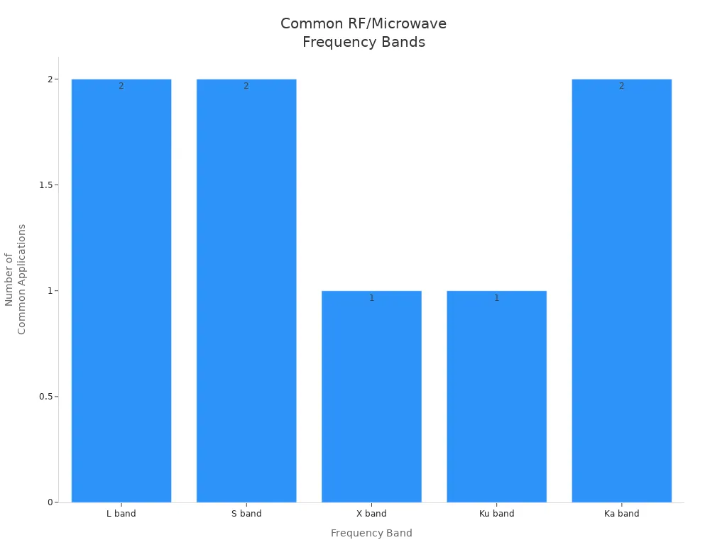
You need to know the frequency range and bandwidth for your project. Different radio-frequency projects use different frequency bands. Cell phones, satellites, and radar systems each use their own bands. The table below lists some common bands and what they are used for:
|
Frequency Band |
Frequency Range |
Common Applications |
|---|---|---|
|
L band |
1 - 2 GHz |
Satellites, GPS, Cell phones |
|
S band |
2 - 4 GHz |
Wi-Fi, Bluetooth, Satellite radio |
|
X band |
8 - 12 GHz |
Radar systems |
|
Ku band |
12 - 18 GHz |
Satellite TV, Police radar |
|
Ka band |
26.5 - 40 GHz |
5G, Microwave backhaul |
Most rf circuit boards work between 500 MHz and 3 GHz. This range is good for antenna size and data. If you use high-frequency signals, your components must match your bandwidth needs. Connectors and probes should handle the highest frequency you use. If you want to upgrade later, pick parts with more bandwidth.
Application Needs
What your project does will help you pick the right parts. Wireless systems need clear signals and little interference. Radar systems need to find and track things well. The table below shows what matters most:
|
Primary Needs |
Key Factors |
|
|---|---|---|
|
Wireless Communication |
Signal clarity, high data rates |
Low insertion loss, bandwidth |
|
Radar Systems |
Target detection, reliability |
Power handling, environmental robustness |
For radio-frequency jobs like 5G or satellite, you need filters to block bad signals. Radar needs parts that work at high frequencies, like 24 GHz or 77 GHz, and can handle lots of power. Good pcb design helps keep noise low and signals strong.
Environment Factors
The environment is important for your project to work well. Temperature changes can make cables get bigger or smaller, which changes signal timing. High humidity can hurt cable jackets and make signals worse. Vibration and shock can break solder joints on your pcb. You should test your design for these problems. Pick materials that can handle heat and moisture. For example, car radar projects need pcb materials that stay strong at high frequencies and in tough places. Thinking about the environment helps your project last longer and work better.
Tip: Always check your pcb design for environmental problems before you pick your parts.
RF and Microwave Components
Microwave Component Types
Modern rf systems use many microwave components. Each one has a special job. Some make signals stronger. Others change or filter signals. Here are the main types you will see:
|
Component Category |
Examples and Functions |
|---|---|
|
Active Components |
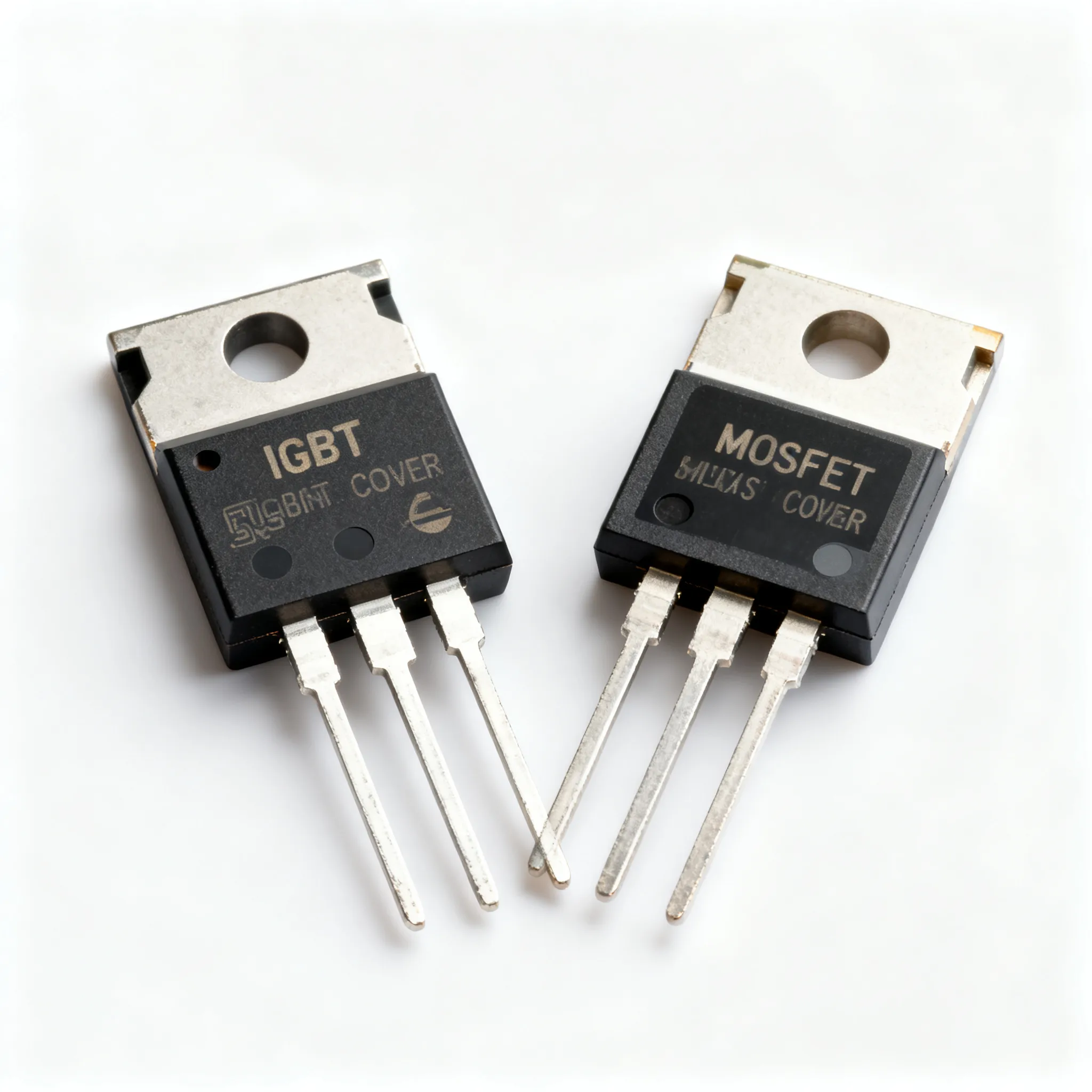
Amplifiers, transistors, integrated circuits (MMICs), high power transmitters |
|
Passive Components |
Resistors, capacitors, inductors, transformers, baluns, couplers, dividers |
|
Frequency Control |
Oscillators, synthesizers, phase shifters, prescalers, frequency multipliers and dividers |
|
Signal Processing |
Mixers, modulators, demodulators, limiters, log amplifiers |
|
Switching and Routing |
Switches, rotary joints |
|
Antenna and RF Interface |
Antennas, connectors, cable assemblies, attenuators, terminations |
|
Specialized Components |
Ferrite components (isolators, circulators), waveguides, YIG devices, tubes (TWTs, klystrons) |
|
Integrated Solutions |
Microwave subsystems, multichip modules, system-on-chip (SoC) |
Amplifiers help weak signals get stronger. Mixers let you change a signal’s frequency. Filters take out signals you do not want. Oscillators and synthesizers make steady frequencies. Switches and couplers send signals to the right place. Antennas send and get signals through the air. All these microwave components are important for your rf and microwave design.
Use Cases
You need to pick microwave components that fit your project. Different jobs use different parts. Here are some common examples:
|
Component Type |
Typical Use Cases |
Application Domains |
|---|---|---|
|
Wideband Compact BDC Module |
Frequency downconversion up to 40 GHz |
COMINT, ELINT, intelligence gathering |
|
V-band Triple-Channel Upconverter |
Secure, high-performance military communications |
Secure military communications (V-band) |
|
Radar Synthesizer |
Fast-hopping frequency synthesis for radar |
Fixed, mobile, man-portable radar systems (D- to X-band) |
|
Radar Converter (Up/Downconverter) |
Dual-conversion, frequency-agile RF conversion |
Radar systems (L- and X-Band), signal processing |
|
Pulse-Amplifier |
Amplification for radar pulses |
Radar systems |
|
RF Selector |
Monitoring and function control of radar systems |
Radar systems |
|
Radar Transponder |
Target practice in C- and X-bands |
Radar training and simulation |
|
WR-28 Amplifier |
RF amplification |
Radar, SIGINT, secure communications |
-
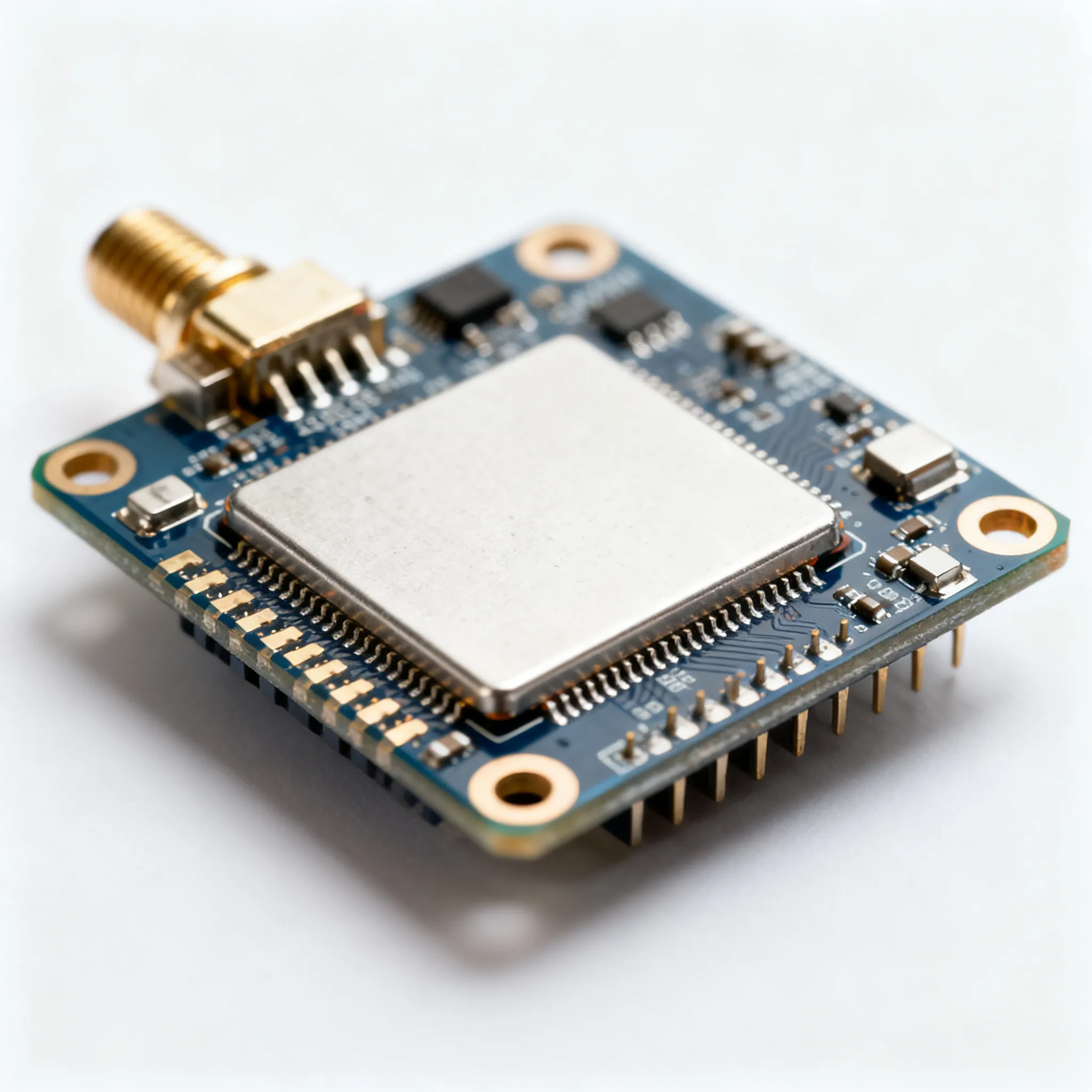
Software-defined radios (SDRs) use lots of microwave parts. You will see LNAs, power amplifiers, IQ up/downconverters, filters, and ADC/DACs in the radio front end. SDRs work in radar, spectrum monitoring, and electronic warfare. The digital back end uses FPGAs to process signals and run security or AI. SDRs can be fixed, mobile, or portable. You can change their size, weight, and power for your project.
-
Wireless communication needs amplifiers for clear signals. Filters block noise. Radar systems use high-frequency amplifiers and mixers to find targets. Secure military radios use upconverters and synthesizers for fast, safe messages. Every job needs the right microwave parts to work well.
Tip: Always check if your microwave parts fit your project’s frequency and signal needs.
Selection Criteria
Pick microwave components that match your design goals. Start by checking the signal frequency and power level. For high-frequency designs, choose parts with low loss and steady performance. The dielectric in your pcb changes how signals move. Class I dielectrics are best for tight tolerance and low loss, like in LC filters. Class II dielectrics are okay if you can accept more change.
-
Engineers look for these things in microwave parts:
-
Low loss tangent to keep signals strong
-
Even dielectric constant for steady impedance
-
Smooth pcb surface to lower ohmic losses
-
High thermal conductivity for better power handling
-
Good match between pcb and part expansion
-
If you work with low-power rf, use amplifiers with low noise and clear signals. For high-power rf, you need amplifiers that can handle more heat and power. High-power designs often use waveguides for better power handling. Low-power designs may use coaxial cables because they are flexible.
|
Aspect |
Low-Power RF Applications |
High-Power RF Applications |
|---|---|---|
|
Power Handling |
Lower power; less heat |
Must handle high power and heat; needs cooling |
|
Thermal Management |
Not very important |
Very important; needs heat sinks or fans |
|
Materials and Manufacturing |
Standard materials |
Special materials for high power and tough places |
|
Interconnect Type |
Coaxial cables |
Waveguides for high power; coaxial for lower power |
|
Nonlinear Effects (PIM) |
Focus on noise and clear signals |
Must avoid distortion and intermodulation |
|
Component Examples |
LNAs, low phase noise amplifiers |
Power amplifiers, attenuators, filters, couplers, terminations |
|
Environmental Robustness |
Moderate |
High; must pass vibration, temperature, and moisture tests |
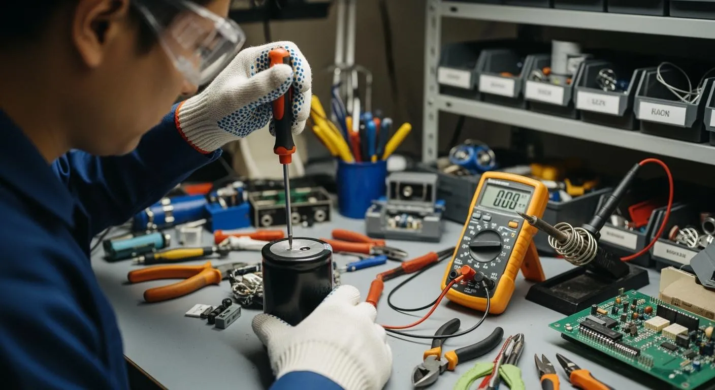
You should always test your microwave parts in real life. Make sure they work with your pcb and signal path. Good choices help your rf and microwave parts last longer and work better.
Component Parameters
When you pick rf components, you need to check some key things. These things help your design work well and stay safe. The most important ones are dielectric constant, insertion loss, power handling, and connector compatibility.
Dielectric Constant
The dielectric constant is very important for pcb materials in rf design. You need to know how it changes with heat, frequency, and direction. This value is not always the same. It can change if your circuit gets hot or if the rf signals go faster. These changes can affect timing, impedance, and phase. If you ignore the dielectric constant, your rf circuit might not work right.
-
The dielectric constant controls how fast rf signals move in pcb materials. A higher dielectric constant slows the signal down. This can mess up timing in your circuit.
-
The dielectric constant also changes the phase of rf signals. This can be a problem if you need exact timing.
-
Impedance depends on the dielectric constant. Lower values help keep impedance steady, which is good for signal quality.
-
High dielectric constant materials can make pcb traces couple more, which can hurt signal quality.
-
The dielectric constant can change because of heat, frequency, and how the material is made. For example, when it gets hotter, the dielectric constant usually goes down.
-
Low dielectric constant materials (less than 4) are best for high-frequency rf circuits. They help signals move faster and keep impedance steady.
-
The dielectric constant also affects insertion loss and signal loss. If you pick the wrong dielectric, your rf performance will get worse.
You should always balance the dielectric constant with other material features. High dielectric constant materials can make smaller circuits, but they can also make your design less stable. Always check how the dielectric constant will change in real life.
Tip: Use low dielectric constant materials for high-frequency rf designs. This keeps your signals fast and your impedance steady.
Insertion Loss
Insertion loss tells you how much signal you lose when your rf signal goes through a part or material. You want this number to be as low as you can. High insertion loss means your signal gets weaker, which can hurt your system.
-
The dielectric constant of your pcb materials affects insertion loss. If you use materials with a high dielectric constant, you may lose more signal.
-
Insertion loss also depends on how good your rf parts are. Bad connectors, cables, or filters can add extra loss.
-
You should always test your rf design to measure insertion loss. Use a network analyzer to check how much signal you lose at each step.
If you keep insertion loss low, your rf system will work better. Your signals will stay strong, and your parts will last longer.
Power Handling
Power handling is the most rf power a part or material can take without breaking. You need to know this number for every part of your rf design. If you send too much power through a part, it can get too hot or break.
-
The dielectric strength of your pcb materials sets the limit for how much voltage and power your traces can handle.
-
Some materials can take more power because they move heat away better. These materials help keep your rf parts cool.
-
You should always check the power handling of your amplifiers, filters, and connectors. If you use a part with low power handling in a high-power rf system, it might fail.
For high-power rf designs, use materials with high dielectric strength and good thermal features. Add heat sinks or fans if you need them. Always test your system at full power to make sure your parts can handle it.
Note: Never go over the power handling of your rf parts. This keeps your system safe and working well.
Connector Compatibility
Connector compatibility is very important for good rf performance. You need to pick connectors that match your system’s frequency, impedance, and size needs. Using the wrong connector can cause signal loss, reflection, or even damage.
|
Examples of Connector Types |
|
|---|---|
|
Micro |
MCX, MMCX, SMP, SMPM, SSMP |
|
Subminiature |
BMA, SMA, SMB, SMC, SMS, QLA, QMA, 1.0/2.3 |
|
Small |
BNC, BNO, BNT, MHV, SHV, TNC |
|
Medium |
N, QN, 4.3/10, 4.1/9.5 |
|
Large |
7/16, EIA |
|
Precision |
3.5mm, 2.92mm, 2.4mm, 1.85mm, 1.0mm |
You will see many connector types in rf and microwave systems. BNC connectors work well for low-frequency signals up to 4 GHz. SMA connectors are common for high-frequency rf signals up to 18 GHz. Precision connectors like 3.5mm can go even higher, up to 34 GHz. Each connector has a special job.
-
Always match the impedance of your connectors (usually 50 or 75 ohms) to your cables and parts. This keeps signal reflections and loss low.
-
Make sure your connectors fit your cables and system. Using the wrong size or type can cause damage.
-
Do not use connectors outside their rated frequency range. This can cause signal leaks and bad performance.
-
Choose connectors with the right way to connect for your needs. Threaded connectors like SMA are strong and resist shaking. Bayonet connectors like BNC are easy to connect and disconnect.
If you pick the right connectors, your rf system will work better and last longer. Good connector compatibility also helps you avoid problems like signal loss, distortion, and system failure.
Tip: Always check connector ratings and match them to your rf system’s needs before you build your design.
Material Choices
PCB Materials
You have to pick the right materials for your pcb. Good rf pcb materials help your design work at high frequencies. Different companies make special materials for different uses. The table below lists some popular choices and what they do:
|
Vendor |
Material Type / Specialty |
Dielectric Constant (Dk) Characteristics |
|---|---|---|
|
Isola |
Copper-clad laminates and dielectric prepregs |
Used in RF/microwave; low loss tangent materials |
|
Rogers |
High-frequency laminates, bondplys, prepregs |
Excellent dielectric constant control; low Dk |
|
Arlon |
Polyimide, epoxy, low loss thermoset laminates |
Materials suitable for advanced RF/microwave |
|
Taconic |
Advanced composite materials for microwave/RF |
Low loss tangent, stable dielectric constant |
|
Panasonic |
Megtron high-performance PCB and flex materials |
High frequency suitable; low dielectric loss |
|
Nelco |
High thermal reliability materials |
Designed for high-speed digital and RF applications |
|
DuPont |
Pyralux and high temperature flex materials |
Used in RF flex circuits; low dielectric loss |
PTFE, also called Teflon, is a common rf pcb material. It has a low dielectric constant and does not lose much signal. This makes it great for high-frequency pcb design. You should always pick materials that match your project’s frequency and signal needs. The right materials keep your signals clear and your pcb steady.
Thermal Management
Thermal management is very important for high-frequency pcb design. Heat can hurt your materials and make your pcb not last as long. You need to control heat to keep your rf pcb materials working well. Here are some ways thermal management helps:
-
It stops parts from getting too hot and breaking.
-
Heat makes traces have more resistance, which weakens signals.
-
When it gets hot or cold, materials can grow or shrink. This can crack your pcb.
-
Too much heat can change how materials work and mess up signals.
-
Good thermal management uses smart part placement, thermal vias, and heat sinks.
-
You can use materials that move heat away quickly.
You should always plan for thermal management in your pcb design. This keeps your rf pcb materials safe and your signals strong.
Tip: Keep hot parts apart and use thermal vias to spread heat.
Manufacturability
You need to think about manufacturability when you pick pcb materials. Some materials are easy to cut, drill, and solder. Others need special tools or extra steps. If you pick hard-to-use materials, your pcb may cost more or take longer to make. Always check if your rf pcb materials work with your factory’s process. Good material choices make your pcb design faster and more reliable.
You should balance dielectric properties, thermal needs, and manufacturability. This helps you get the best results from your materials. Smart choices in material selection lead to better performance and easier production.
RF Design Best Practices
Matching and Impedance
You must match impedance in every rf design. When the source and load impedance match, power moves best. If they do not match, you lose signal and waste energy. Bad matching can cause a high standing wave ratio (SWR). This means you lose power and might hurt your transmitter. In receivers, bad matching makes signals weak. You can use LC circuits to help match impedance. Always check the impedance of your lines, antennas, and parts. Use simulation tools to make sure your rf circuit matches well. Matching also keeps your signal strong and helps all parts work together.
Tip: Make sure your transmission line impedance matches your source and load. This stops signal reflections.
Reliability
You want your rf system to last and work in hard places. You can test your parts with special tests. Salt atmosphere tests check if parts rust. Thermal shock tests see if parts survive fast temperature changes. Vibration and shock tests show if parts can handle bumps and shakes. Moisture resistance tests tell you if your design works in wet places. Always use parts that pass these tests for better reliability. In aerospace, engineers use machines to test rf devices for accuracy and signal strength. Regular checks help you find problems early and keep your system safe.
|
Test Method |
Purpose |
|---|---|
|
Salt Atmosphere |
Corrosion Testing |
|
Moisture Resistance |
Humidity Exposure |
|
Thermal Shock |
Temperature Changes |
|
Vibration |
Movement Endurance |
|
Mechanical Shock |
Impact Resistance |
Avoiding Pitfalls
Many engineers make the same mistakes in rf design. You can avoid these problems by following easy steps:
-
Pick the right pcb materials for high-frequency rf signals. Do not use FR-4 for microwave designs.
-
Always use solid power and ground planes to lower noise and keep signals clear.
-
Figure out trace width and spacing to stop signal loss and heat.
-
Group parts by what they do. Keep noisy parts away from sensitive ones.
-
Use fewer vias on high-frequency signal paths.
-
Build a prototype before making lots of boards to find mistakes early.
-
Run design rule checks to stop expensive errors.
-
Handle connectors the right way and check for damage before using them.
-
Plan for good heat flow with thermal vias and heat sinks.
Note: Good planning and careful layout help you keep signals clear and make your rf system last longer.
You can also keep signals strong by not using sharp 90-degree bends in traces. Use solid ground planes and keep traces short and straight. Use EM simulation tools to check your layout. These steps help you connect all parts well and keep signals strong in every rf project.
You can get the best results in your microwave design by following simple steps. First, write down what your pcb needs, like frequency, signal type, and dielectric properties. Pick microwave components that fit your design and try them out with your pcb layout. Always make sure your materials can handle heat and keep their dielectric strength. Use easy guides and tutorials to learn about signal flow, pcb assembly, and microwave materials. Ask experts for help if you have problems or want better performance. Choosing the right pcb materials, signal paths, and dielectric values helps you make microwave systems that work well and last a long time.
FAQ
What is the most important factor when choosing RF components?
You should check the frequency range first. Make sure your parts work at the right frequencies. This helps you stop signal loss and bad performance.
How do you reduce signal loss in your RF design?
Pick PCB materials that do not lose much signal. Keep your traces short. Use connectors and cables that fit your frequency. Test your design with a network analyzer to find weak spots.
Can you use regular PCB materials for microwave circuits?
No, you should not use FR-4 for high-frequency designs. Use special materials like PTFE or Rogers laminates. These materials help keep your signals strong and steady.
Why does connector type matter in RF projects?
Connector type changes signal quality and how well your system works. If you pick the wrong connector, you might lose signal or get reflections. Always match connector ratings to your frequency and impedance needs.