SMAJ180A/TR13 Design-In Guide: Selecting the Right TVS Diode for Your Circuit
Expert guide on SMAJ180A/TR13 Design-In Guide: Selecting the Right TVS Diode for Your Circuit. Technical specs, applications, sourcing tips for engineers and buyers.
SMAJ180A/TR13 Design-In Guide: Selecting the Right TVS Diode for Your Circuit
When Board Space Shrinks and Transient Threats Grow: The Case for Purpose-Built TVS Diodes
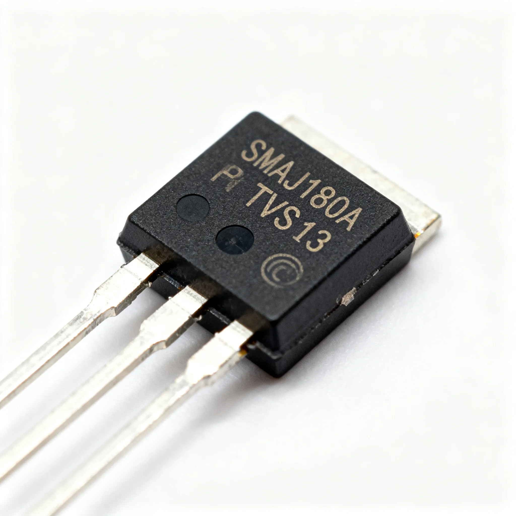
You’re packing more functionality into less PCB real estate. At the same time, your power rails face increasingly aggressive voltage transients — from inductive load switching, ESD strikes, and residual surge events. A poorly chosen TVS diode can result in field failures, costly re-spins, or over-engineered protection that adds unnecessary capacitance and cost. The SMAJ180A/TR13 from the SMAJ platform gives you a 400 W peak pulse power rating in a compact SMA (DO-214AC) footprint, purpose-built to clamp high-energy spikes on 180 V rails while consuming minimal board area. Littelfuse SMAJ datasheet confirms the device’s ability to absorb 400 W under the 10/1000 μs waveform, making it a reliable first line of defense for industrial power supplies, telecom rectifiers, and high-voltage LED drivers.
In the real world, a transient can reach the kilovolt range in nanoseconds. Without a suppressor, that energy forces its way into downstream DC/DC converters, microcontrollers, and sensitive analog front ends. The SMAJ180A/TR13 is designed to transition from a high-impedance state to a low-impedance conduction path within picoseconds, shunting excess current to ground and clamping the voltage to a safe level. This is not a generic Zener; it is a purpose-built silicon avalanche diode with a large junction area designed to handle repetitive surges without degradation. The SMAJ series, including the SMAJ180A/TR13, has proven itself in thousands of designs, and the specific 180 V standoff rating addresses a voltage niche that is underserved by commodity 5 V or 12 V protectors.
Key Takeaway: The SMAJ180A/TR13 is a compact, 400 W TVS diode with a 180 V standoff voltage, optimized for industrial and telecom rails where space is tight but transient energy is significant.
Decoding TVS Specifications: Breakdown, Clamping, and Peak Pulse Power
To select the right suppressor, you need to interpret the three critical parameters: VBR (breakdown voltage), VC (clamping voltage), and IPP (peak pulse current). The SMAJ180A/TR13 offers a standoff voltage (VR) of 180 V, a minimum breakdown voltage of 200 V, and a maximum clamping voltage of 292 V at a peak pulse current of 13.7 A (10/1000 μs waveform). These numbers tell a story: the device will not conduct at your normal operating voltage, but will begin to break down slightly above 200 V, turning on fully to limit the voltage to 292 V during a surge. That’s exactly the behavior you want for a 180 V DC rail where the nominal voltage may fluctuate between 170 V and 190 V under load. Eaton SMAJ datasheet provides analogous parameters, confirming the industry-standard footprint and electrical consistency.
The table below summarizes the key electrical and thermal characteristics you need to vet before committing to a layout. All values are sourced from the manufacturer’s public datasheet.
| Parameter | Value | Unit/Notes |
|---|---|---|
| Standoff Voltage (VR) | 180 | V — maximum DC operating voltage |
| Breakdown Voltage (VBR) min. @ IT = 1 mA | 200 | V |
| Clamping Voltage (VC) max. @ IPP = 13.7 A | 292 | V — 10/1000 μs waveform |
| Peak Pulse Power (PPP) 10/1000 μs | 400 | W |
| Peak Pulse Current (IPP) | 13.7 | A |
| Maximum Reverse Leakage @ VR | 1 | μA |
| Junction Capacitance (Typical) | 15 | pF |
| Operating Junction Temperature | -55 to +175 | °C |
| Package | SMA (DO-214AC) | Surface mount |
| Reel Quantity (TR13 suffix) | 5,000 | pcs per 13-inch reel |
At first glance, the 292 V clamping voltage might seem high, but remember that the transient is measured at the leads of the TVS. Inductive ringing and PCB trace inductance can add to the voltage seen by the protected IC. That’s why layout is critical (see Section 4). The 400 W rating is for a 10/1000 μs pulse — a standard telecom surge profile. For shorter pulses, such as ESD (8/20 μs), the device can handle significantly higher peak current because the energy is lower. The datasheet’s pulse derating curves provide the detailed mapping. Leakage current of 1 μA at 180 V means the TVS contributes negligible quiescent power loss, an important consideration in high-voltage systems where every microamp of leakage adds to thermal budget and standby power consumption.
SMAJ180A/TR13 vs. Alternatives: Matching Voltage and Power to Your Rail
The 180 V standoff of the SMAJ180A/TR13 is purpose-built for industrial and telecom rails, but the same SMAJ package accommodates a wide voltage range. For a 12 V or 24 V rail, a lower-voltage member such as the SMAJ18A/TR13 offers an 18 V standoff and a 29.2 V clamping voltage, still rated at 400 W. The following comparison matrix helps you weigh the SMAJ180A/TR13 against other voltage options and bidirectional variants, based on real datasheet data. SMAJ18A/TR13 details and SMAJ180 overview confirm the parametric accuracy.
| Comparison Metric | SMAJ180A/TR13 (Unidirectional, 180 V) | SMAJ18A/TR13 (Unidirectional, 18 V) | SMAJ180CA (Bidirectional, 180 V) | Selection Criteria & Failure Boundary |
|---|---|---|---|---|
| Standoff Voltage (VR) | 180 V | 18 V | ±180 V | Must exceed max DC rail voltage including tolerances and ripple. For 180 V rails, 180 V is the minimum; 200 V or 220 V may be needed if the rail has a wide tolerance. For 12 V or 24 V, use 15 V or 26 V parts. |
| Breakdown Voltage (VBR min.) | 200 V | 20 V | 200 V (both polarities) | VBR must be above the maximum operating voltage to avoid nuisance conduction. The 20 V minimum for SMAJ18A/TR13 ensures it stays off on a 12 V rail. |
| Clamping Voltage (VC max.) | 292 V @ 13.7 A | 29.2 V @ 13.7 A | 292 V (both directions) | The downstream IC or converter must withstand the clamping voltage. For a 180 V to 12 V converter, the 292 V spike must be within the input transient rating. The 29.2 V must be below the max input of a 12 V POL regulator. |
| Peak Pulse Power (PPP) | 400 W | 400 W | 400 W | Identical thermal capability. Higher voltage devices handle lower current; the energy is the same. The 400 W limit is for the 10/1000 μs waveform; derate for temperature. |
| Leakage Current (max.) | 1 μA | 1 μA | 1 μA | Low leakage is critical for battery-powered or low-power standby systems. All variants share similar leakage. |
| Polarity | Unidirectional | Unidirectional | Bidirectional | Unidirectional for positive DC rails; bidirectional for AC lines or signals that swing negative (e.g., RS-485, CAN, audio). |
From this comparison, you can see that the SMAJ180A/TR13 is the right choice for a positive 180 V rail, while the lower-voltage SMAJ18A/TR13 is ideal for a 12 V rail. If you need to protect a balanced signal line or an AC input, the CA suffix bidirectional version is the tool. However, note that the bidirectional device will have a slightly higher clamping voltage due to the series diode drop in the reverse direction, and its capacitance may be different. Always verify the exact datasheet curves for the specific part number you intend to use.
Tip: When powering a 180 V DC bus that feeds multiple isolated converters, place a SMAJ180A/TR13 at the entry point before the first filter inductor. This clamps the bulk energy and prevents the downstream converters from seeing a destructive overvoltage. The 400 W rating can absorb energy from a 2 Ω impedance surge of moderate duration, but it is not a substitute for a gas discharge tube in primary telecom protection; it is a secondary protector.
Designing In the SMAJ180A/TR13: Layout, Thermal, and Derating Pitfalls
Even the best TVS diode will fail to protect your circuit if it’s not placed correctly. The golden rule: place the SMAJ180A/TR13 as close as physically possible to the connector or the point of entry of the transient. Long traces between the TVS and the connector add parasitic inductance that can allow the voltage to spike far above the clamping voltage before the TVS turns on. A 10 mm trace can add 10 nH of inductance, which at a 13.7 A current and a 1 ns rise time can produce an additional voltage drop of L×dI/dt = 10 nH × 13.7 A/1 ns = 137 V on top of the clamping voltage. That’s enough to kill a downstream converter rated for 300 V.
Use wide, short traces (at least 0.5 mm wide for the 180 V rail to minimize impedance) and place the TVS directly between the line and the ground plane with a solid via connection. The ground side of the TVS must connect to the same quiet ground as the protected circuit. Avoid sharing ground return paths with high-current switching nodes that could inject noise onto the TVS reference. The following table summarizes the thermal derating of peak pulse power based on the Littelfuse SMAJ datasheet derating curve. The 400 W rating is valid only at 25 °C; above that, the device can handle proportionally less power.
| Ambient Temperature (°C) | Peak Pulse Power Derating (% of 400 W) | Available PPP (W) | Design Implication |
|---|---|---|---|
| 25 | 100 | 400 | Full rating; ensure adequate copper pour for heat sinking. |
| 50 | 85 | 340 | If the board operates in a hot enclosure, derate accordingly. |
| 75 | 70 | 280 | Consider using two TVS in parallel, but beware of sharing due to differences in VBR. |
| 100 | 55 | 220 | At 100 °C the device can still handle moderate transients, but margin is reduced. |
| 125 | 40 | 160 | A 180 V rail in a sealed industrial box may reach this temperature; evaluate worst-case surge energy. |
| 150 | 25 | 100 | Approaching the limit; consider a larger package or a higher power rating TVS. |
| 175 | 0 | 0 | Maximum junction temperature; no power handling capability. |
For steady-state power dissipation, the SMAJ180A/TR13 can handle about 0.2 W at 25 °C on a standard FR-4 board with minimal copper. If the device experiences frequent repetitive surges, the average power must be calculated and kept below this limit. Add a small series resistor (e.g., 10 Ω, 1 W) between the connector and the TVS to limit the current during sustained events, but be mindful of the voltage drop on the normal load current. IC-Online can help you find the exact resistor as well as the TVS.
Checklist for robust layout:
- Place the SMAJ180A/TR13 within 5 mm of the input connector pins.
- Use a solid ground plane on an inner layer to minimize inductance; connect the TVS cathode directly to the power trace and the anode to the ground plane with at least two vias.
- Keep the trace width between the TVS and the protected circuitry at least 0.5 mm to handle the high surge current momentarily.
- Add a 0.1 μF ceramic capacitor in parallel with the TVS to absorb very fast edges, but verify that the total capacitance does not affect signal integrity.
- If the ambient temperature exceeds 50 °C, evaluate the derating curve and consider a power derating factor of 0.8 or more.
SMAJ180A/TR13 Selection and Application FAQs
Here are the most common questions senior engineers and procurement buyers ask when evaluating the SMAJ180A/TR13 for a design.
Q: What is the difference between the SMAJ180A and SMAJ180CA?
The ‘A’ suffix denotes a unidirectional TVS, clamping positive transients only — ideal for a positive DC rail. The ‘CA’ version is bidirectional, clamping both polarities, and is used for AC lines or signals where polarity can reverse. For a 180 V DC bus, the unidirectional SMAJ180A/TR13 is the correct choice because it will not conduct during normal operation and will clamp only positive surges. The bidirectional version would need to withstand the full 180 V in reverse bias, which is similar, but its capacitance and clamping characteristics differ slightly.
Q: How does the SMAJ180A/TR13’s clamping voltage affect my downstream DC/DC converter?
The maximum clamping voltage VC of 292 V (at 13.7 A, 10/1000 μs) must be lower than the absolute maximum input voltage of the downstream converter. Any converter on a 180 V rail must withstand that brief spike. If your converter’s input rating is 250 V, the 292 V clamp could be destructive. In that case, you may need to add a second TVS with a lower clamping voltage, or a series inductor and capacitor to filter the spike. Always check the converter’s transient immunity rating; many high-voltage converters are designed to survive 300 V for short durations, but verify the datasheet.
Q: Can I use the SMAJ180A/TR13 for automotive load dump protection?
Not directly. Standard load dump pulses (ISO 16750-2) can deliver much higher energy than the 400 W rating of the SMAJ180A. For 12 V systems, a lower‑voltage TVS with 1500 W or more is needed. The 180 V rating may be useful in 24 V truck systems combined with additional protection, but always verify against the actual test pulse profile. The central load dump pulse can have a peak voltage of 202 V for a 24 V system and an energy of several joules, requiring a 1500 W or 3000 W device. The SMAJ180A/TR13 can serve as secondary protection after a bulk suppressor, but never as the sole load dump clamp.
Q: What thermal derating should I apply to the SMAJ180A/TR13 at elevated ambient temperatures?
The peak pulse power derates linearly from 400 W at 25 °C to 0 W at 175 °C, as shown in the earlier table. For steady‑state power dissipation, the device handles about 0.2 W at 25 °C. In a typical industrial enclosure at 60 °C, you have roughly 340 W pulse capability. If your measured surge energy is 0.5 joules, and the expected pulse width is 50 μs, you can calculate the required power and compare with the derated rating. Always refer to the derating curve in the Littelfuse SMAJ datasheet.
Q: What are typical lead time and availability for the SMAJ180A/TR13?
The SMAJ180A/TR13 is a popular SMA‑packaged TVS, widely stocked by distributors. Lead times are typically in the range of 4–8 weeks, but always verify with authorized distributors, as supply can fluctuate. The ‘TR13’ suffix indicates a 13‑inch reel with 5,000 pieces, which is ideal for high-volume production. For prototyping, you can request a partial reel or samples. Visit IC-Online to check current availability and request a quote.
Q: How does the SMAJ180A/TR13 compare to other 400 W TVS diodes in the same package?
The Brightking SMAJ180A/TR13 shares the same electrical ratings as the Littelfuse SMAJ180A and Eaton SMAJ180A: 180 V standoff, 400 W peak pulse power, and clamping around 292 V. The ‘TR13’ reel packaging is specific to Brightking, but the component is functionally interchangeable with equivalent parts from other vendors. You can use the same footprint and the same design rules. However, always verify the exact clamping voltage and leakage current from the manufacturer’s datasheet to ensure compatibility with your circuit’s tolerances.
References & Further Reading
- Littelfuse SMAJ TVS Diodes Datasheet — Detailed specifications, derating curves, and package dimensions.
- Eaton SMAJ TVS Diode Datasheet — 400 W transient voltage suppressor, electrical and thermal data.
- SMAJ18A/TR13 Datasheet & Product Details (Utmel) — Lower-voltage member of the SMAJ family for reference.
- SMAJ180 TVS Diode Overview (Utmel) — CAD model and parametric comparison.
- IC-Online — Electronic Components Sourcing & RFQ — Request a quote, upload your BOM, and find the SMAJ180A/TR13 and related components.
- ISO 16750-2: Road vehicles — Environmental conditions and testing for electrical and electronic equipment — Part 2: Electrical loads. (Refer to the standard for load dump test pulse definitions.)
- Application Note: “TVS Diode Selection for High-Voltage Industrial Power Supplies” — available from major semiconductor manufacturers such as TI and Analog Devices.
Selecting the right TVS diode is about balancing standoff voltage, clamping voltage, and surge rating with layout constraints. The SMAJ180A/TR13 delivers a proven 400 W solution for 180 V rails in a compact SMA package, but your design must account for thermal derating, trace inductance, and the downstream converter’s transient immunity. By following the layout rules and verifications outlined here, you can achieve robust protection without over-engineering. Ready to secure your design? Request a quote or upload your BOM on IC-Online — the platform supports mixed BOMs and flexible MOQs, helping you source the SMAJ180A/TR13 and all supporting components quickly.