

Smart Utility Meter Components: Metrology ICs, Communications, and Reliable Supply
Smart Utility Meter Components: Metrology ICs, Communications, and Reliable Supply
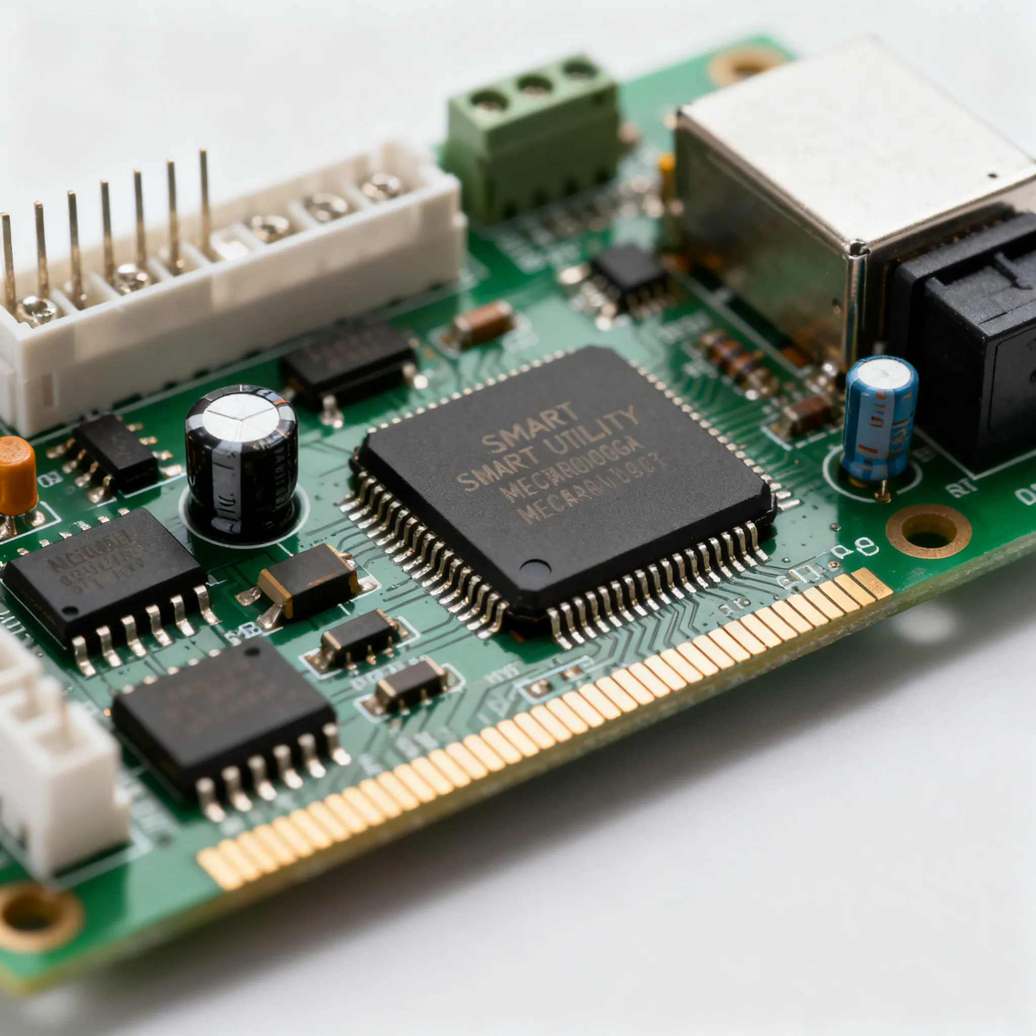
Smart Utility Meter Components: Metrology ICs, Communications, and Reliable Supply
Why Metrology IC Sourcing Has Become a Strategic Bottleneck for Smart Meter Rollouts
Large-scale smart meter deployments are accelerating worldwide, but the semiconductor supply environment has turned the metrology front-end into a critical pinch point. Procurement teams now face extended lead times that can stretch well beyond 20 weeks for dedicated energy measurement ICs, forcing a re‑evaluation of how accuracy, long‑term reliability, and Bill of Materials (BoM) cost are balanced. A comprehensive guide from Onomondo underscores that minimizing the complete BoM—including physical components and communication protocols—is a make-or-break exercise for device manufacturers. At the same time, new connectivity options such as NB‑IoT and LTE‑M are reshaping the communications portion of the meter, as detailed by M2M Server’s analysis of cellular IoT efficiencies. These two forces—a constrained metrology chip pipeline and a rapidly evolving wireless landscape—mean that a dual focus on metrology IC selection and supply chain planning is now essential for any utility or meter manufacturer. Even a well‑specified meter can miss its rollout window if the front‑end IC is unavailable, and a meter unable to support the required communication link will fail utility qualification regardless of its measurement performance.
How Metering SoCs and Dedicated ICs Tackle Accuracy and Integration
Metrology ICs sit at the heart of every smart meter. They perform high‑precision measurement of voltage and current, compute active and reactive energy, and must meet stringent accuracy classes defined in standards such as IEC 62053‑21/22. The STPM01 and STPM10 devices from ST exemplify a dedicated metrology approach; they integrate all the core circuitry required to implement a class 1 electricity meter, including programmable gain amplifiers, high‑resolution ADCs, and a digital signal processor that calculates active energy, apparent energy, and RMS values. This self‑contained architecture lets engineers drop a proven front‑end onto a board and pair it with the microcontroller of their choice.
In contrast, integrated solutions like Microchip’s PIC32CXMT and SAM4C MCUs combine the metrology front‑end with an application microcontroller and communication peripherals on a single die. The PIC32CXMT integrates a 32‑bit Arm® Cortex®‑M4F core, a dedicated metrology co‑processor, and an on‑chip LCD controller, while the SAM4C family targets multi‑phase meters with dual 32‑bit cores and a metrology engine that supports up to four independent current channels. The table below compares the key parameters that engineers evaluate when selecting between a dedicated metrology IC and an integrated SoC for a typical 1‑phase or 3‑phase design.
| Parameter | STPM10 (Dedicated IC) | Microchip PIC32CXMT (Integrated SoC) | Selection Note |
|---|---|---|---|
| Accuracy class | Class 1 (IEC 62053‑21), 0.5% active energy error over dynamic range | Class 0.5S capable with metrology co‑processor | Class 0.5S needed for high-accuracy industrial and grid metering |
| Number of current channels | 2 (single‑phase, bidirectional) | Up to 4 independent channels (supports 3‑phase) | 3‑phase meters require ≥3 current measurement channels |
| Integrated MCU | None (external MCU required) | 32‑bit Arm Cortex‑M4F @ 200 MHz | Determines protocol stack and application layer location |
| ADC resolution / type | 2‑channel, 24‑bit Σ‑Δ ADCs | 4‑channel, 24‑bit Σ‑Δ ADCs with metrology co‑processor | Higher resolution supports wider dynamic range with low‑value shunts |
| Communication interfaces | SPI, 2‑wire serial | SPI, I²C, UART, USB, Ethernet, CAN | Influences the choice of external communication module (NB‑IoT, LTE‑M) |
| On‑chip memory | None (relies on external MCU) | Up to 2 MB Flash, 512 KB SRAM | Integrated memory simplifies firmware for complex protocol stacks |
| Anti‑tamper features | Current and voltage tamper detection | Magnetic tamper, neutral missing, phase reversal detection | Utility specifications often mandate a specific tamper list |
| Supply voltage range | 3.0 V – 5.5 V | 1.71 V – 3.6 V (core), I/O compatible with 3.3 V | Affects power supply design and isolation requirements |
| Package | TSSOP‑20 | LQFP‑100 to LQFP‑144 | Larger package for SoC may increase PCB area but reduce chip count |
The STPM10’s compact footprint and dedicated metrology engine make it a favourite for cost‑sensitive single‑phase meters where the MCU and communication interface are already defined. On the other hand, the PIC32CXMT’s integrated memory and peripheral set allow a single chip to handle metrology, DLMS/COSEM protocol stack, and a TCP/IP stack for an Ethernet‑connected meter, eliminating the need for an external host processor. The decision ultimately hinges on whether the design team values integration and certification speed over the flexibility of mixing and matching the metrology front‑end with the most suitable communication processor.
Dedicated Metrology ICs vs. Integrated MCUs: Which Architecture Fits Your Meter?
Choosing between a discrete metrology IC paired with an external MCU and an all‑in‑one SoC affects BOM count, design flexibility, certification effort, and long‑term scalability. Microchip’s integrated platform can reduce PCB area by merging the application layer, communications layers, and metrology functions into a single device, while a separate STPM01/10 plus an independent MCU offers more freedom to swap communication modules without requalifying the entire meter. The communication technology selection—whether NB‑IoT, Cat‑M, or LPWA, as discussed by M2M Server—further influences the decision, because integrated solutions may lock in a specific protocol stack or require a particular modem interface. For industrial versus commercial deployments, YTL’s technical selection guide warns that misspecifying the metering architecture can cause measurement inaccuracies, premature hardware failure, and data bottlenecks, making the architectural comparison a genuine make‑or‑break evaluation.
| Comparison Metric | Dedicated IC (STPM10 + External MCU) | Integrated SoC (Microchip PIC32CXMT/SAM4C) | Selection Criteria & Failure Boundary |
|---|---|---|---|
| BOM component count | Higher: 2 major ICs + passives | Lower: single IC integrates MCU, metrology, and often LCD driver | Choose integrated if you need to minimize PCB size and pick‑and‑place steps; dedicated if you want separate sourcing paths. |
| Design flexibility | Excellent: MCU can be upgraded or swapped for different communication modules | Limited: metrology and MCU upgrade must be done together | If you anticipate protocol changes (NB‑IoT to 5G NR‑Lite), a dedicated IC preserves the metrology investment. |
| Certification effort | Moderate: metrology IC is pre‑certified, but full meter certification includes the MCU and communication module | Lower: vendor provides pre‑certified reference designs covering the entire board | Integrated platforms can cut months from utility approval cycles if the design matches the reference. |
| Communication module upgrade path | Straightforward: replace the MCU or the modem card without touching the metrology section | More complex: the SoC’s integrated interfaces may limit modem choices or require a new firmware build | Designs that must support multiple communication link types per UK smart metering specs benefit from a modular architecture. |
| Typical deployment | Commercial and industrial meters, multi‑tenant gateways, meters requiring field‑replaceable communication cards | High‑volume residential 1‑phase meters, cost‑optimized 3‑phase meters with fixed communication | For residential meters in regulated markets, an integrated SoC often wins on cost; for C&I, flexibility trumps integration. |
If a utility mandates that the communication card be field‑replaceable and mapped to the meter serial number, as detailed in the BSES Delhi technical specification, a two‑chip architecture simplifies compliance. The metrology front‑end remains on the main board, while the communication card hosts the modem and its own MCU, allowing the utility to swap cards without recalibrating the meter. In contrast, an integrated SoC may require the entire meter to be opened and re‑certified, a process that can introduce additional cost and field‑service complexity.
Sourcing and Design Decisions That Prevent Meter Deployments from Stalling
Practical advice for engineers and buyers centres on securing supply, managing integration risks, and safeguarding the metrology front‑end. The BSES Delhi technical specification illustrates the real‑world integration requirements—pin‑out, voltage levels, and mapping of meter serial numbers to communication cards—that must be locked down early. Similarly, the UK smart metering equipment technical specification reinforces the need to support specific communication link types, which directly impacts component selection. For circuit protection, the Bourns white paper on monitoring and protecting smart meter circuitry provides concrete guidance on shielding current‑sense metrology inputs from transients using a combination of differential filtering and transient voltage suppression. Finally, the Onomondo BoM‑focused approach reminds teams to treat the entire bill of materials—including connectivity—as a single cost‑optimisation exercise, not a series of isolated choices.
To translate these requirements into a robust sourcing strategy, consider the following five steps:
- Qualify a second‑source metrology path. Identify a pin‑compatible alternative or an integrated MCU‑with‑metrology that can serve as a drop‑in replacement if your primary IC goes on allocation. This prevents a single‑vendor bottleneck.
- Lock down the communication interface early. Map the UART, SPI, or I²C pins and voltage levels required by the modem against the metrology board, using utility specs such as the BSES tender as a checklist. Any mismatch here will delay field trials.
- Protect the analogue front‑end from the start. Follow Bourns’ recommendations: place differential filtering close to the shunt, use TVS diodes on the input lines, and keep the current‑sense traces short and symmetrical. Even a class‑1 IC will degrade to class‑2 performance if the layout picks up common‑mode noise.
- Treat the BoM as a system. The cost of the cellular module, antenna, and SIM provisioning can exceed the metrology IC’s cost. Optimize the entire BoM, including firmware licences and connectivity, rather than squeezing the last cent out of the metrology chip alone.
- Hold safety stock for critical line items. Based on 12–30‑week lead‑time swings, buffer at least 8–12 weeks of demand for the metrology IC and the communication module. Work with authorised distributors to secure allocation slots and avoid broker‑sourced parts that may not meet traceability requirements.
The table below summarises the most common supply‑chain risks and their mitigation options.
| Risk | Mitigation Strategy | Benefit |
|---|---|---|
| Single‑source metrology IC lead‑time surge | Qualify a pin‑compatible alternative (e.g., alternative metrology IC or MCU with integrated metrology) and allocate a portion of the production volume to the second source. | Reduces production stoppage risk; provides negotiation leverage. |
| Communication module incompatibility | Use the pin‑out and voltage‑level requirements from utility specifications (e.g., BSES, UK SMETS) to define the interface before board layout. | Ensures seamless integration and avoids costly re‑spins. |
| Current‑sensor noise degrading accuracy | Implement differential filtering, TVS protection, and star‑ground layout as detailed in the Bourns white paper. | Maintains class‑1 accuracy in the field despite transients and EMI. |
| BOM cost overruns due to fragmented purchasing | Treat the entire meter BoM—including connectivity and firmware—as a single cost‑optimisation exercise (Onomondo approach). | Improves margin and aligns procurement with design goals. |
| Firmware and calibration incompatibility between metrology ICs | Build an abstraction layer that isolates the metrology driver; budget time for re‑characterisation of gain, phase, and offset over temperature. | Enables multi‑source strategy without re‑writing the entire application. |
Smart Meter Metrology Sourcing: Answers to the Questions Engineers and Buyers Ask
Q: How do I confirm a metrology IC meets IEC 62053‑21/22 accuracy classes without relying solely on the datasheet?
Look for independent certification reports and meter‑socket‑level test data from accredited labs. Many vendors provide reference designs that have already passed utility qualification; the STPM10, for example, demonstrates class 1 capability in production. However, the datasheet alone cannot guarantee system‑level accuracy. You must verify the complete signal chain—including the current sensor (shunt, CT, or Rogowski coil), PCB layout, and power supply noise—in your own prototype. Testing across the full operating temperature range and with the expected burden is essential, because thermal drift in the shunt or common‑mode noise can easily push a class‑1 IC into class‑2 territory.
Q: What are the typical lead times for metrology ICs from ST and Microchip, and how can I build a buffer?
Lead times for dedicated metrology ICs and integrated MCUs have swung between 12 and 30 weeks during semiconductor shortages. While current conditions may have improved, it is prudent to plan for the longer end of that range. To build a buffer, qualify a pin‑compatible alternative upfront—for instance, an STPM10 and a corresponding device from a second vendor, or a Microchip PIC32CXMT as a fallback if your primary metrology IC is unavailable. Hold safety stock for critical line items, and work with authorised distributors to secure allocation slots through a rolling forecast. If your design allows, an MCU with integrated metrology can mitigate single‑vendor risk by giving you a second sourcing path within the same footprint.
Q: Should I choose a single‑chip integrated MCU with metrology or a separate metrology IC for a 1‑phase residential smart meter?
For high‑volume residential meters, an integrated solution like Microchip’s PIC32CXMT can reduce BOM cost and simplify certification because the vendor supplies a pre‑tested reference design. The single‑chip approach also saves PCB area and pick‑and‑place steps, which is significant when you are shipping millions of units. However, if you need to support multiple communication protocols—such as NB‑IoT today and a future LTE‑M or 5G NR‑Lite upgrade—or if the utility requires a field‑replaceable communication card, a discrete metrology IC with an external MCU offers more flexibility. The metrology front‑end remains unchanged, and you can swap the communication module without re‑certifying the metrology portion, saving both time and cost in the long run.
Q: How do I ensure the communication module (NB‑IoT, LTE‑M) will work seamlessly with my chosen metrology IC?
Map the required UART, SPI, or I²C interfaces and voltage levels against the metrology board’s pin‑out, as detailed in utility specifications like the BSES tender. Verify that the metrology IC’s data output rate matches the module’s reporting interval—typical interval for NB‑IoT is 15–30 minutes, but real‑time pricing may require more frequent updates. Test the end‑to‑end latency under worst‑case load, including the firmware stack’s buffering and the wireless network’s retransmission delays. A design review that includes the modem vendor’s reference layout and the metrology IC’s layout guidelines helps avoid signal integrity issues on the serial lines.
Q: What are the most common mistakes when integrating current sensors with a metrology front‑end?
Engineers often underestimate the impact of shunt resistor placement, thermal drift, and common‑mode noise. The Bourns white paper shows that a combination of differential low‑pass filtering and transient voltage suppression is essential to maintain accuracy. Shunt resistors must be placed as close as possible to the IC’s differential inputs, with Kelvin‑sense routing to eliminate voltage drops along the trace. Even a small thermocouple effect at the shunt‑to‑PCB junction can introduce a drift that makes a class‑1 meter fail over temperature. Layout guidelines from the IC vendor must be followed exactly; otherwise, the metrology IC’s performance is compromised, and the meter may be downgraded to class 2 in utility testing.
Q: How do I handle firmware and calibration when switching between dedicated metrology ICs from different suppliers?
Plan for an abstraction layer in the firmware that isolates the metrology driver. Calibration routines are often proprietary, so budget time for re‑characterisation of gain, phase, and offset over the full operating temperature range. A modular metrology board that can be swapped during development accelerates the comparison between suppliers. Because each IC has its own register map, calibration coefficients, and compensation algorithms, you cannot simply port the configuration; you will need to run the full calibration procedure—usually at multiple current levels and power factors—on a golden sample meter.
Need components or PCBA support for Smart Utility Meter products? IC-Online helps smart-device OEMs with sourcing and board-level supply — see our Smart Device Solutions or contact our team for a BOM review.
References & Further Reading
- Microchip Technology – Smart Energy Metering
- Communication Technologies in Smart Metering (M2M Server)
- Commercial vs Industrial Smart Meters: Complete Technical Selection Guide (YTL)
- Building compliant and reliable IoT-based smart metering systems (Onomondo)
- BSES Delhi Technical Specification for Smart Meters (PDF)
- ST Brochure – Smart Grid Distribution and Smart Meters
- UK Smart Metering Equipment Technical Specifications (PDF)
- ← Previous ArticleNext Article >>
Related Articles
 Blog
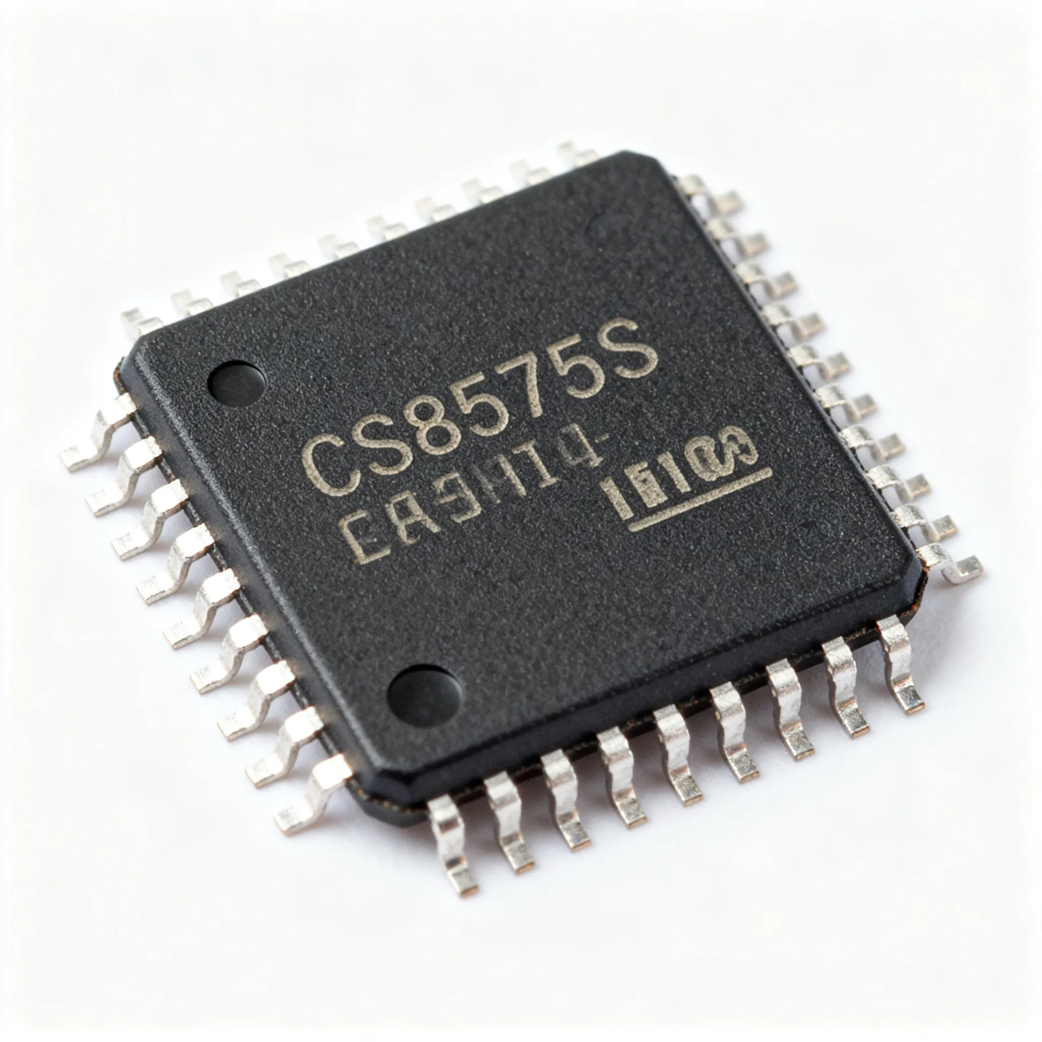
BlogCS8575S Supply Risk Assessment: What to Ask Before You Buy
Assess CS8575S sourcing risks before you buy. RFQ questions on traceability, date codes, testing, alternatives, and supply continuity for procurement teams.
 Blog
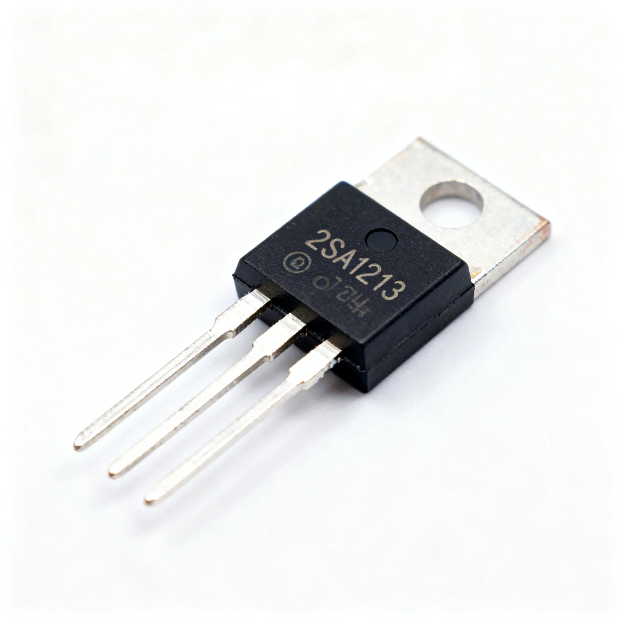
Blog2SA1213 Obsolescence Risk Checklist: Confirm Lifecycle Status Before Sourcing
2SA1213 lifecycle and obsolescence risk checklist. What to verify before redesign or last-time-buy — without assuming drop-in replacements.
 Blog
BlogHow VSC Works in Modern Cars and Why It Matters
What is VSC on a car? VSC (Vehicle Stability Control) is an electronic system that brakes individual wheels and cuts engine power to maintain traction. The VSC light indicates active intervention or a fault.
 Blog
BlogUnderstanding DC Circuits and Their Practical Uses
What is a dc circuit? It's a closed loop with constant voltage and unidirectional current, powering everyday electronics. See its practical uses in electronics.
 Blog
BlogExcess Inventory: How Component Engineers Can Turn Surplus into Supply Chain Resilience
Practical guide for buyers and engineers: Excess Inventory: How Component Engineers Can Turn Surplus into Supply Chain Resilience. Sourcing, risk, and selection notes.
 Blog
BlogWhat Does a Resonator Do
What does a resonator do? It generates and stabilizes a specific frequency for timing, signal generation, and filtering in electronic circuits.