The PCM Audio Format A Simple Story Of Sound And Circuits
The pcm audio format is a precise set of instructions. These instructions guide a circuit, telling it how to conve
The pcm audio format is a precise set of instructions. These instructions guide a circuit, telling it how to convert a physical sound wave into a sequence of digital numbers. We will follow a single sound wave on its journey through the electronic components. Each step in the process corresponds to a specific circuit's job.
Think of pcm as creating a digital blueprint for sound. Key measurements on this blueprint, like sampling rate and bit depth, define the final audio precision.
Key Takeaways
- PCM turns sound waves into digital numbers. It uses a blueprint to change physical sound into digital audio.
- Sampling takes many snapshots of a sound wave. The sampling rate tells how many snapshots it takes each second.
- Quantization measures each snapshot's voltage. Bit depth shows how precise this measurement is.
- An Analog-to-Digital Converter (ADC) changes analog voltage into binary numbers. A Digital-to-Analog Converter (DAC) changes numbers back to voltage.
- The PCM format organizes digital sound data. This makes it easy for devices to store and play back audio.
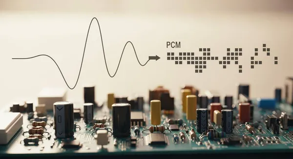
What is the PCM Audio Format?
Pulse-Code Modulation, or PCM, is the standard method for converting a continuous analog signal into a sequence of digital numbers. Imagine a sound wave traveling from a microphone. The pcm audio format provides the blueprint for turning that physical wave into digital audio. This process creates a faithful numerical representation of the original sound.
From Analog Sound to Digital Signal
The journey of the pcm audio format from theory to consumer products is a story of innovation. Its history highlights a consistent drive for higher fidelity and reliability in telecommunications and audio.
- 1937: British engineer Alec Reeves first conceived of PCM to improve voice communication security and efficiency.
- 1967: Japan's NHK developed the first experimental PCM recorder, a major step toward practical digital recording.
- 1971: Engineers at Denon used an NHK system to produce the world's first commercial digital recordings.
- 1977: Sony launched the PCM-1, the first digital audio processor marketed to consumers, allowing them to record using video cassette recorders.
Early pioneers saw its potential for robust, high-quality transmission.
Although they saw equipment for PCM as more complex than other forms of modulation, Oliver, Pierce, and Shannon concluded that “in all, PCM seems ideally suited for multiplex message circuits, where a standard quality and high reliability are required.”
The Core Steps: Sampling and Quantization
The conversion from analog to the pcm format relies on two fundamental steps. These steps work together to capture and measure the sound wave, turning it into structured audio data.
- Sampling: This is the process of taking discrete measurements, or "snapshots," of the sound wave's amplitude at regular time intervals. Each snapshot captures the signal's voltage at a specific moment.
- Quantization: This process assigns a discrete numerical value to each sample. It measures the amplitude of every snapshot and converts that measurement into a binary number.
We will explore how circuits perform these two critical actions in the following sections.
Sampling: Capturing The Sound Wave
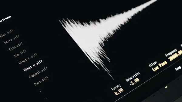
The first step in creating our digital blueprint is sampling. This process captures the continuous, flowing sound wave and converts it into a series of distinct points. Each point represents the wave's voltage at a precise moment in time.
Think of sampling as a high-speed camera. It takes thousands of "snapshots" of the sound wave every second. The sequence of these snapshots forms a flip-book that outlines the wave's shape.
The Role of The Sampling Rate
The sampling rate dictates how many snapshots the circuit takes per second. It is measured in Hertz (Hz). A higher sampling rate means more snapshots, resulting in a more detailed and accurate outline of the original sound wave. But how many snapshots are enough?
The answer lies in the Nyquist-Shannon Sampling Theorem. This fundamental principle of digital signal processing states that to perfectly reconstruct a signal, you must sample it at a rate at least twice its highest frequency component. This is often called the "2x rule." Since the upper limit of human hearing is around 20,000 Hz, the minimum sample rate required to capture all audible frequencies is 40,000 Hz, or 40 kHz.
- To capture a 10,000 Hz mosquito buzz, you must sample at 20,000+ Hz.
- To record the full range of human hearing (20–20,000 Hz), a sampling rate of 40,000+ Hz is necessary.
This is why the 44.1 kHz rate was chosen for the Compact Disc (CD) format. It provides just enough information to cover the full spectrum of human hearing. Other standards exist for different applications. Blu-ray Discs often use multiples of 48 kHz, and professional recording studios commonly record at 96 kHz to provide more "breathing room" for audio processing.
Sampling below the Nyquist rate causes an error called aliasing. This artifact occurs when high frequencies in the original signal are incorrectly interpreted as lower frequencies. These "reflected" frequencies were not in the original sound, creating a coarse, metallic distortion that prevents accurate reproduction.
Circuit Action: Clock and Sample-and-Hold
Two key electronic components work together to perform sampling: a clock and a sample-and-hold circuit.
-
The Clock (Crystal Oscillator): The clock acts as the system's metronome. It is typically a crystal oscillator, a component that generates an extremely stable and precise timing pulse. This pulse tells the circuit exactly when to take each snapshot. The frequency of these pulses is the sampling rate. For high-fidelity audio, this timing must be incredibly accurate.
Parameter Typical Value Frequency Stability ±10 ppm (parts per million) Frequency Range 1-125 MHz Operating Voltage 1.8-3.3 V Any deviation in this timing, known as clock jitter, introduces errors. Even tiny variations, measured in picoseconds (trillionths of a second), can degrade the performance of an Analog-to-Digital Converter's filters. This timing inconsistency can cause high-frequency information to "splatter" across the audio band, creating audible spurious tones and noise.
-
The Sample-and-Hold (S/H) Circuit: This circuit receives the timing pulse from the clock. When the pulse arrives, the S/H circuit instantly captures the microphone's analog voltage and holds it steady. This "frozen" voltage is then passed along to the next stage of the process: quantization. The S/H circuit ensures that the voltage being measured doesn't change during the measurement process, guaranteeing an accurate snapshot.
Together, the clock's relentless pulse and the sample-and-hold circuit's quick capture action form the electromechanical heart of the sampling process.
Quantization: Measuring The Voltage

After the sample-and-hold circuit captures a voltage snapshot, the system must measure it. This measurement process is called quantization. It converts the continuous analog voltage of each sample into a discrete digital number.
Think of quantization as using a ruler to measure the height of each voltage snapshot. The bit depth determines the number of measurement marks on that ruler. More marks mean a more precise measurement.
Understanding Bit Depth
Bit depth defines the resolution for each measurement. It specifies the number of binary digits (bits) used to represent the value of each sample. A higher bit depth provides more possible values, allowing for a more accurate representation of the original analog voltage. This increased accuracy directly impacts the recording's quality.
Bit depth determines the potential dynamic range of a recording. Dynamic range is the difference between the loudest possible signal and the quietest. Each bit of resolution adds approximately 6.02 dB to the dynamic range. This relationship also defines the quantization noise floor, which is the inherent noise introduced by the rounding process.
- 16-bit Audio: Offers 65,536 (2¹⁶) possible measurement levels. This provides a theoretical maximum dynamic range of about 96 dB, which is sufficient for consumer formats.
- 24-bit Audio: Provides over 16.7 million (2²⁴) levels. This lowers the noise floor significantly, offering a theoretical dynamic range of about 144 dB. This gives audio engineers more headroom and flexibility during production.
The discrepancy between the true analog voltage and the closest available digital value is called quantization error. This error manifests as a low-level hiss or noise in the final signal. Higher bit depths reduce this error by providing more precise measurement steps, resulting in a cleaner recording with less distortion.
Different applications use different bit depths to balance quality and file size.
| Audio Format | Common Bit Depth |
|---|---|
| CD Audio | 16-bit |
| High-Resolution Audio | 24-bit |
| Professional Recording | 32-bit floating point |
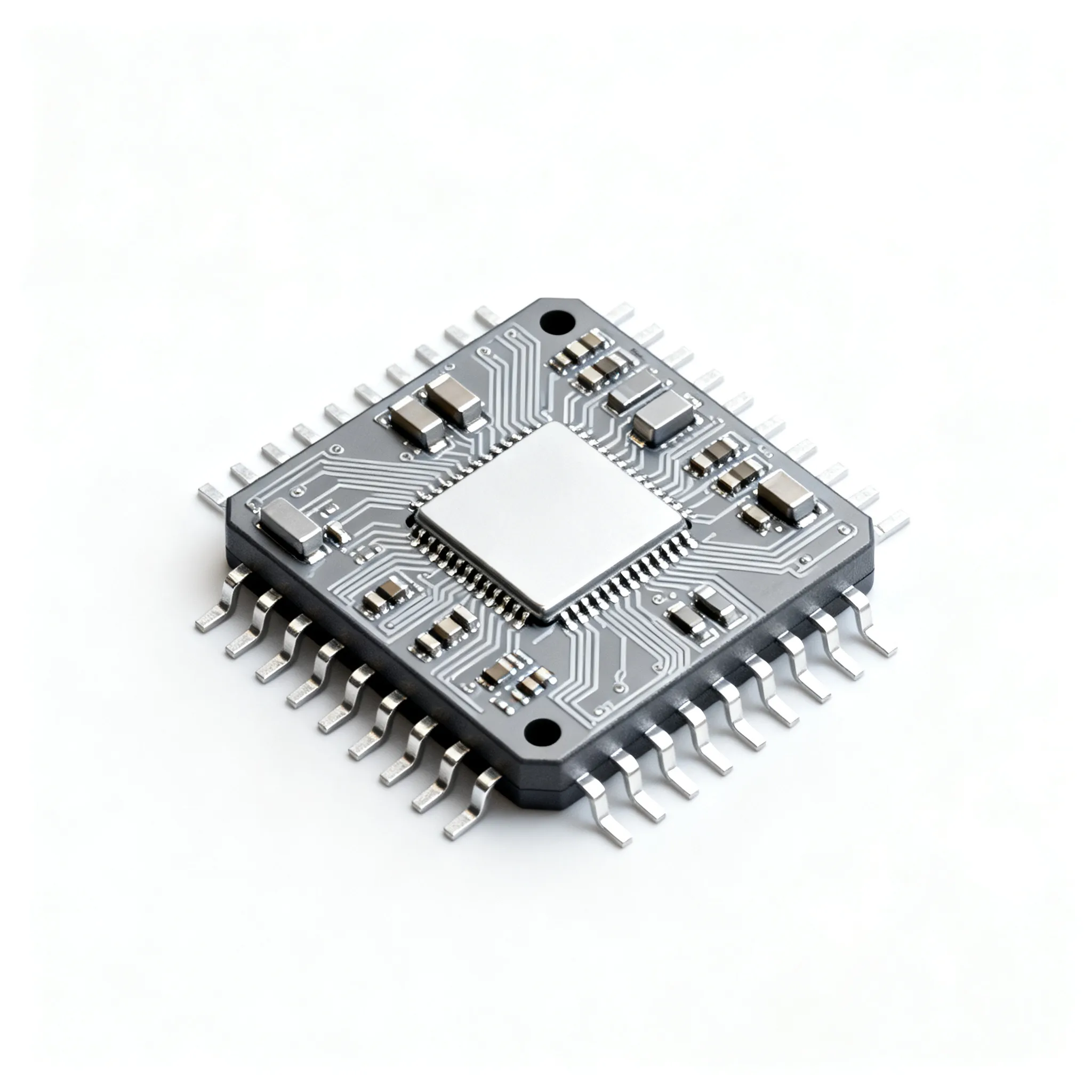
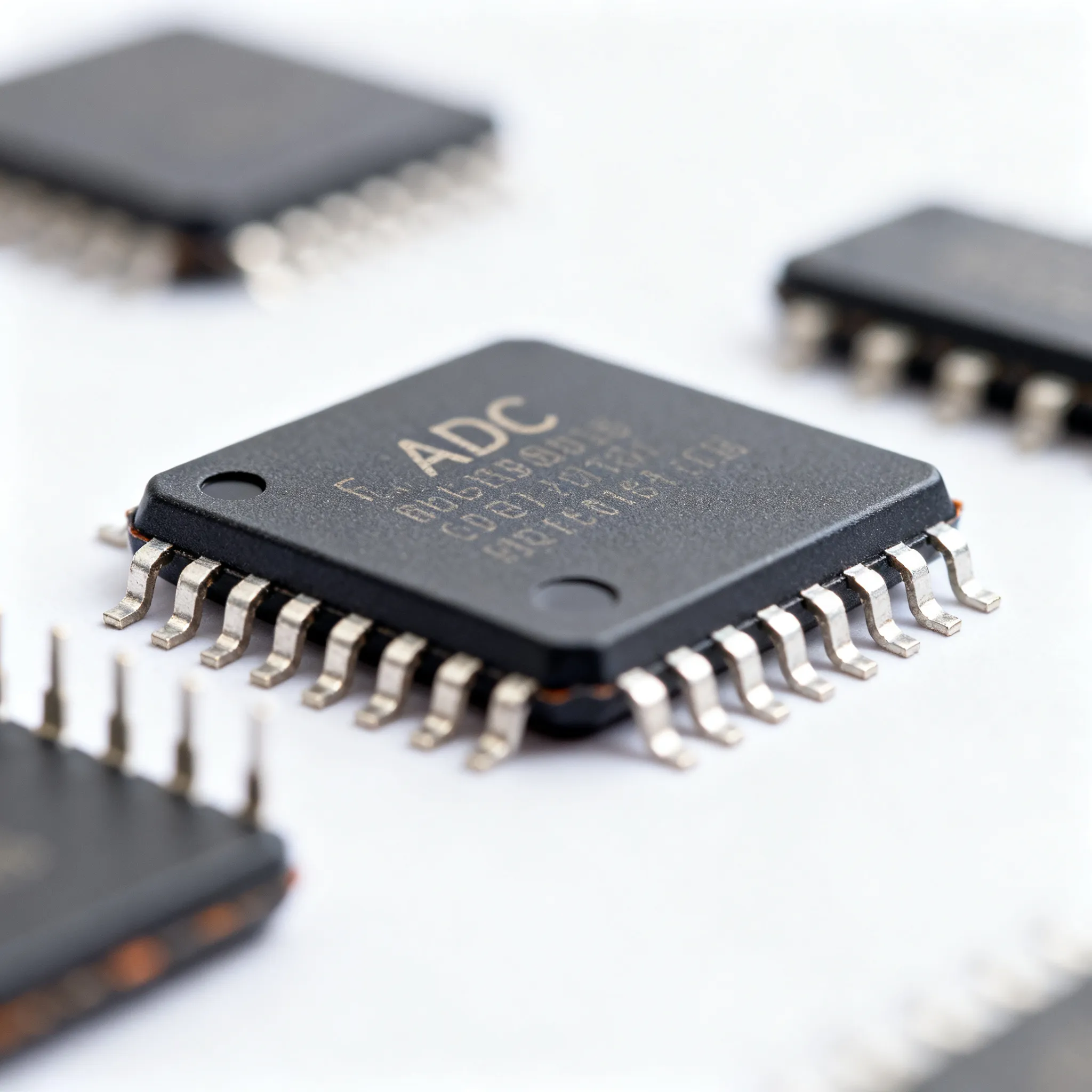
Circuit Action: Quantizing Voltage into PCM Data
The circuit that performs quantization is the Analog-to-Digital Converter (ADC). An ADC takes the steady voltage from the sample-and-hold circuit and outputs a binary number. One of the fastest types of ADCs is the flash ADC.
A flash ADC works almost instantaneously using a simple, powerful architecture.
- Voltage Ladder: The circuit contains a series of resistors connected to a reference voltage. This creates a "ladder" with different, precise voltage levels at each "rung."
- Comparators: A comparator is a simple circuit that compares two voltages. A flash ADC has a dedicated comparator at each rung of the voltage ladder. Each one compares the input sample's voltage to its specific reference voltage.
- Encoder Logic: If the sample's voltage is higher than a comparator's reference voltage, the comparator outputs a '1'. Otherwise, it outputs a '0'. A digital encoder circuit then reads this pattern of 1s and 0s from all the comparators and translates it into a single binary number.
This binary number is the final piece of PCM audio data for that one sample. This process repeats for every sample, thousands of times per second, generating a continuous stream of numbers that represents the original sound wave. In commercial audio hardware, like the X-Fi Fatal1ty Pro sound card, a dedicated ADC integrated circuit such as the WM8775SEDS performs this critical conversion.
Encoding: Structuring The Digital Stream
The ADC delivers a stream of binary numbers, but this raw data lacks context. To become useful, these numbers must be organized into a structured digital stream. Encoding adds the necessary metadata and arranges the data in a standardized way for storage or transmission.
Organizing the PCM Format
The pcm format requires a "wrapper" or container to be understood by software and hardware. This container holds essential metadata. A common example is the WAV file, which uses a header to describe the audio within. This header acts like a table of contents for the raw data that follows.
A standard WAV file header for uncompressed PCM audio specifies critical parameters. These parameters ensure correct playback.
| Offset (Bytes) | Field | Description |
|---|---|---|
| 22 | Number of Channels | 1 for Mono, 2 for Stereo |
| 24 | Sample Rate | The sampling frequency (e.g., 44100) |
| 34 | Bits per Sample | The bit depth (e.g., 16 or 24) |
| 36 | Subchunk2 ID | "data" marker, indicating the start of audio |
For multi-channel audio, the data itself is interleaved. Samples from each channel are placed sequentially.
- Stereo (2.0): The stream alternates between the left and right channels (L, R, L, R...).
- Surround (5.1): The pattern expands to include all channels, such as Left, Right, Center, LFE, Left Surround, and Right Surround.
This organization ensures that all channel information for a single point in time is grouped together.
Circuit Action: Shift Registers and Logic Gates
The ADC outputs all bits of a single sample simultaneously in a parallel format. However, for transmission to another chip, this data must be converted into a serial stream—one bit after another. This is the job of a Parallel-In, Serial-Out (PISO) shift register.
- The shift register receives a 'Load' signal, telling it to accept the parallel audio data from the ADC.
- Once loaded, a clock pulse tells the register to "shift" the data out one bit at a time.
- This serial stream is then sent over a connection using a standard like the I2S protocol.
The I2S (Inter-IC Sound) protocol is a common interface for transferring the pcm audio format between integrated circuits, such as from an ADC to a processor. These digital circuits are built from fundamental components called logic gates. Gates like AND, OR, and NOT perform basic Boolean logic, enabling the complex operations of a shift register to control and manipulate the flow of binary data.
Playback: Recreating PCM Audio
The journey from a digital blueprint back to a physical sound wave is the final, critical step. Playback reverses the recording process. It takes the structured stream of numbers and instructs a circuit how to reconstruct the original analog signal, ready to be sent to speakers or headphones.
From Numbers Back to Voltage
The core of playback is converting the digital numbers back into analog voltages. This task belongs to the Digital-to-Analog Converter (DAC). A DAC reads each binary number in the pcm format and generates a precise, corresponding voltage level. Each bit in the binary number has a specific weight. The DAC sums these weighted values to produce the final analog output. For example, the binary number 10011 becomes the analog value 19 after the DAC processes the weighted bits (16 + 0 + 0 + 2 + 1).
Different DAC architectures exist, each with distinct sonic characteristics.
- R-2R DACs: These use a resistor ladder network for direct conversion. They are often favored for their smooth, natural, and organic sound.
- Delta-Sigma DACs: These employ oversampling and noise shaping to achieve high resolution. They are known for a precise, detailed, and analytical sound.
The choice of DAC technology significantly influences the final character of the pcm audio.
Circuit Action: DAC and Low-Pass Filter
In a practical circuit, a microcontroller might read pcm audio format audio data from an SD card. It then sends this digital stream to a dedicated DAC integrated circuit using a standard like i2s. A popular choice for this task is the pcm5102 chip, which can directly drive headphones.
The DAC's output is not a smooth curve. It is a series of flat voltage steps, creating a "stair-step" approximation of the sound wave. This raw signal contains unwanted high-frequency noise. A final low-pass filter is required to smooth these steps and remove the artifacts.
This entire spectrum must not be passed on to the player amplifier and loudspeaker. Even though the frequencies above 20 kHz are inaudible, they would overload the player amplifier and set up intermodulation products with the baseband frequencies...
The filter removes these high frequencies, reconstructing the original, smooth analog waveform. This ensures a clean signal is sent to the amplifier, preventing distortion and protecting the equipment. The combination of a DAC like the pcm5102 chip and a well-designed low-pass filter is essential for high-fidelity playback.
The PCM format is more than an abstract standard; it is a direct instruction set for circuit behavior. This journey reveals how fundamental electronic actions create the digital audio we hear every day. Continuous innovation in integrated circuits makes this process more efficient, enabling high-quality sound in ever-smaller devices. The result is a tangible digital blueprint where one minute of CD-quality stereo sound occupies about 10 MB of data.
- Sampling Rate is the speed of the system's clock.
- Bit Depth is the precision of the ADC and DAC.
- The Data Stream is the serialized output of logic gates.
This perspective uncovers the elegant and physical relationship between the music we stream and the circuits that bring it to life.
FAQ
What is the difference between PCM and MP3?
PCM is an uncompressed audio format. It is a direct digital representation of the analog sound wave. MP3 is a compressed format. It removes parts of the audio data that humans are less likely to hear, resulting in a much smaller file size but some loss of quality.
Why do different devices use different sampling rates?
Different applications have different needs for audio quality and file size.
- 44.1 kHz: Standard for CDs, covering the full range of human hearing.
- 48 kHz: Common in video and professional audio for better processing.
- 96 kHz: Used in high-resolution audio for maximum fidelity.
Is higher bit depth always better?
For listening, 16-bit audio is generally sufficient. 24-bit audio provides a lower noise floor and more dynamic range. This is most beneficial for audio engineers during recording and mixing, as it offers more flexibility and headroom to work with before the final master is produced.
What is uncompressed audio?
Uncompressed audio, like PCM in a WAV file, contains all the original data captured during the analog-to-digital conversion. No information is removed to save space. This ensures the highest possible fidelity but results in very large file sizes compared to compressed formats like MP3 or AAC.