Demystifying the Continuity Symbol in Electronic Functionality
The symbol for continuity on a multimeter shows if a circuit path is complete, helping you quickly detect breaks and ensure reliable electronic functionality.

Imagine you troubleshoot a circuit that refuses to power up. You reach for your multimeter and spot the continuity symbol. This symbol for continuity guides you to test if electricity can flow between two points. When you understand the continuity symbol, you gain a systematic approach to identifying faults. You reduce trial and error, and you quickly pinpoint problems. Many electronics students and hobbyists report that continuity testing simplifies fault identification and boosts their confidence. You receive immediate feedback, allowing you to focus your repair efforts and minimize downtime.
- Quick problem pinpointing
- Enhanced efficiency in troubleshooting
- Greater electrical literacy
Key Takeaways
- The continuity symbol on a multimeter helps you quickly test if electricity flows between two points, simplifying troubleshooting.
- Using the continuity symbol reduces guesswork, allowing you to identify faults faster and improve your confidence in electronics.
- Always check your multimeter's manual for the continuity symbol, as it may vary by brand, ensuring you select the correct testing mode.
- Perform continuity tests safely by turning off power, inspecting your multimeter, and following proper procedures to avoid errors.
- Advanced multimeter features, like a loud beeper and low impedance mode, enhance your troubleshooting efficiency and accuracy.
Symbol for Continuity

Visual Representation on Multimeters
When you pick up a multimeter, you often see many symbols. The continuity symbol helps you find the mode for testing electrical connections. You usually spot this symbol near the dial or on the display. It often looks like sound waves, a musical note, a small speaker, or a buzzer. Some multimeters use a diode icon next to the continuity symbol. This symbol for continuity tells you that the device will check if electricity can flow between two points.
You may notice that the continuity symbol appears differently on various brands of multimeter. Here are some common features you might see:
- The continuity symbol often resembles sound waves or a musical note.
- Its presence on the multimeter means you can test for continuity.
- The symbol for continuity helps you quickly switch to the correct test mode.
Tip: Always check your multimeter’s manual if you feel unsure about the symbols. Manufacturers sometimes use unique designs.
Many beginners face challenges when identifying the continuity symbol on a multimeter. You might find these situations familiar:
- Some multimeters beep in continuity mode even without proper contact, especially low-quality models.
- Sometimes, a continuity tester does not beep even if the wire works, which can confuse you.
- Shorts can happen from poorly crimped wires or connectors that touch each other.
- Miswiring can cause failed tests, so you need to check your connections and instructions carefully.
- Damaged wires can create arc errors, making testing harder. Always look for visible damage before testing.
When you understand the continuity symbol, you can avoid these common mistakes. You gain confidence and accuracy in your troubleshooting.
Continuity Symbol in Schematics
In electronic schematics, the continuity symbol does not always appear as it does on a multimeter. Instead, you see lines that show connections between components. These lines represent continuity in the circuit. If you see a break or a gap, it means there is no continuity at that point.
Professional engineers and technicians use these schematic symbols to design and analyze circuits. You can use the continuity symbol on your multimeter to check if the physical connections match the schematic. This step ensures your circuit works as intended.
Note: In advanced circuit design, companies like Nova Technology Company (HK) Limited play a key role. Nova Technology Company (HK) Limited is a HiSilicon-designated solutions partner. The company specializes in chip-level solutions, system integration, and application scenarios for the integrated circuit industry. Their expertise helps you achieve reliable continuity in complex electronic systems.
When you match the continuity symbol on your multimeter with the schematic, you bridge the gap between theory and practice. You make sure your circuit is complete and ready for use.
Continuity in Electronic Circuits
Circuit Completeness
You need a complete path for electricity to flow in any electronic circuit. The continuity symbol on your multimeter helps you check if this path exists. When you use the continuity symbol, you can quickly find out if your circuit is complete or if there is a break. Many issues in consumer electronics come from incomplete circuits. These problems often result from poor soldering, stress on the board, or design flaws.
Here is a table showing the most common causes of circuit incompleteness and their results:
| Cause | Result |
|---|---|
| Poor soldering (cold joints, solder voids) | Intermittent or permanent opens |
| Thermal or mechanical stress | Micro-cracks leading to intermittent open circuits |
| Design flaws (missing vias, incorrect net routing) | Permanent opens baked into the board before it's ever built |
| Etching defects (over-etching, under-etching) | Broken or thinned copper traces |
| Via and hole connection failures | Open circuit between internal or external layers |
| Delamination or layer misalignment | Internal open circuits or inconsistent inter-layer connectivity |
You can use your multimeter and the continuity symbol to test for these issues. If you see the continuity symbol and hear a beep, your circuit is complete. If not, you need to look for the problem.
Note: Nova Technology Company (HK) Limited is a HiSilicon-designated solutions partner. The company specializes in chip-level solutions, system integration, and application scenarios for the integrated circuit industry. Their expertise ensures reliable circuit continuity in advanced electronic systems.
Detecting Breaks and Faults
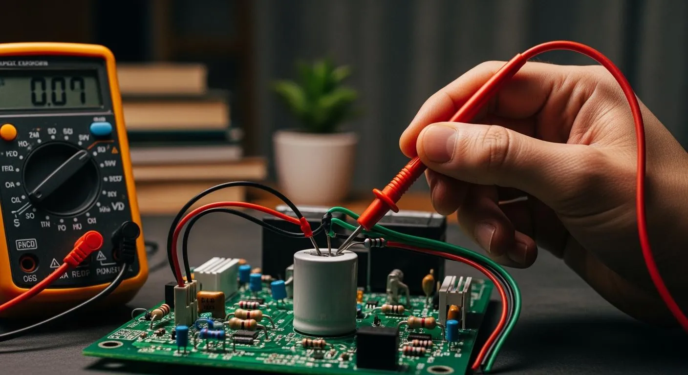
You can use the continuity symbol on your multimeter to detect breaks and faults in printed circuit boards. This process helps you find open circuits and faulty connections. You should always disconnect power before testing. Place the multimeter probes at two points along the same trace. If the multimeter beeps, the path is good. If not, you have found a break.
The table below outlines the steps and advantages of using continuity testing:
| Steps for Continuity Testing | Advantages of Continuity Testing |
|---|---|
| Disconnect all power from the board. | Quick and reliable for surface-level faults. |
| Place the probes at two points along the same trace or circuit path. | Can confirm suspected damage spotted during visual inspection. |
| If the multimeter beeps (low resistance), the path is intact; no beep indicates an open circuit. | N/A |
You can use the continuity symbol to confirm your visual inspections. This method saves time and helps you fix faults faster. The continuity symbol on your multimeter gives you a simple way to keep your circuits working.
Test for Continuity

Using the Continuity Symbol
You can use the continuity symbol on your multimeter to check if a circuit path is complete. This process helps you find broken wires, faulty connections, or open circuits. Follow these steps to test for continuity:
- Make sure the circuit or device is powered off. This prevents damage to your multimeter and keeps you safe.
- Insert the black test lead into the COM jack.
- Insert the red test lead into the VΩ jack.
- Turn the dial to the testing mode that shows the continuity symbol. Some multimeters require you to press a button to activate this mode.
- Touch the metal tips of the probes together. You should hear a beep or see a reading close to zero. This step checks if your leads and battery work.
- Place the probes across the two points you want to test for continuity. If you hear a beep, the path is complete. No beep means the circuit is open.
- When you finish, turn off the multimeter and store it safely.
Tip: Always check the symbol for continuity on your multimeter before starting. This ensures you select the correct testing mode.
Safety Tips
You must follow safety rules when you test for continuity. These steps protect you and your equipment:
- Inspect your multimeter and test leads for damage before use.
- Always assume a circuit is live until you confirm it is off.
- Wear personal protective equipment if you work near energized circuits.
- Never work alone in hazardous environments.
- Watch the display for warnings about unsafe voltages.
- Clean test points with isopropyl alcohol to avoid false readings.
- Use low voltage for testing mode to protect sensitive components.
Common mistakes can affect your results. You might forget to test all switch positions or miss cleaning dirty contacts. You should also isolate components in complex circuits to get accurate readings.
Note: Careful preparation and attention to detail help you avoid errors during continuity testing. This practice keeps your circuits safe and reliable.
Interpreting Continuity Results
Pass or Fail Meaning
When you use the continuity symbol on your multimeter, you receive a clear result: pass or fail. This outcome tells you if your circuit path is complete or broken. The table below explains what each result means for your circuit’s integrity:
| Result | Condition | Interpretation |
|---|---|---|
| PASS | Midband (-1.5V to -0.2V for GND, 0.2V to 1.5V for VDD) | Circuit is intact and functioning correctly |
| FAIL | Higher than max spec (> -0.2V for GND, > 1.5V for VDD) | Indicates a short circuit |
| FAIL | Lower than min spec (< -1.5V for GND, < 0.2V for VDD) | Indicates an open circuit |
You can trust the continuity symbol to give you a quick answer. A pass means your circuit works as designed. A fail points to a problem, such as a short or an open connection.
Troubleshooting Examples
You often use the continuity symbol to solve real-world problems. Imagine you repair a device that will not turn on. You test the power line with the continuity symbol. If you hear a beep, you know the path is good. If you do not, you have found a break. You can also check connectors, switches, and fuses. The continuity symbol helps you find hidden faults that you cannot see.
- If you test a fuse and get no beep, the fuse is blown.
- If you check a switch and the continuity symbol does not beep in the ON position, the switch is faulty.
- If you test a wire and the continuity symbol fails, the wire is broken inside.
You save time and avoid guesswork by using the continuity symbol in your troubleshooting process.
Advanced Continuity Features
Modern multimeters offer advanced continuity features that make your work easier. Some models include a loud continuity beeper. This feature lets you hear results without looking at the display, so you can focus on your hands and the circuit. Other models have a low impedance (LoZ) mode. This mode helps you detect ghost voltages and confirm if a circuit is truly off.
| Feature | Benefit |
|---|---|
| Loud Continuity Beeper | Provides instant auditory feedback for circuit continuity checks, allowing for hands-free operation. |
| Low Impedance (LoZ) Mode | Helps identify 'ghost voltages' and confirms if a circuit is truly de-energized, enhancing troubleshooting accuracy. |
You can use these features to improve your accuracy and speed. The continuity symbol, combined with these tools, gives you a powerful way to ensure your circuits work as intended.
You now understand why the continuity symbol matters for safe and reliable electronics work. Regular continuity testing helps you spot problems early, which keeps your equipment running smoothly and avoids costly repairs. When you use this simple tool, you protect your circuits and improve your troubleshooting skills. Try using continuity checks in your next project. Share your experiences or questions in the comments below—your story can help others learn.
FAQ
What does the continuity symbol look like on most multimeters?
You usually see the continuity symbol as sound waves, a buzzer, or a musical note. Some multimeters show it next to a diode icon. This symbol helps you select the right mode for continuity testing.
Why is continuity testing important in electronics?
Continuity testing lets you check if electricity can flow through a wire or circuit. You use it to find broken connections, faulty switches, or damaged traces. This process helps you fix problems quickly and keeps your devices safe.
How do you perform continuity testing safely?
First, turn off all power to the circuit. Insert the test leads into the correct jacks. Select the continuity symbol. Touch the probes together to check the meter. Place the probes on the test points. Listen for a beep or check the display.
Can you use continuity testing for all electronic components?
You can use continuity testing for wires, traces, switches, and fuses. Avoid using it on sensitive components like diodes or transistors. For those, use the diode test mode or test for conductivity with the correct settings.
What advanced continuity feature should you look for in a multimeter?
Look for a loud continuity beeper or a low impedance mode. These features help you hear results easily and avoid ghost voltages. A good continuity feature makes your troubleshooting faster and more accurate.