A fresh take on audio volume potentiometer design - EDN Magazine
Upgrade your audio volume potentiometer design with modern solid-state variable resister circuits that eliminate wiper noise and improve signal purity.
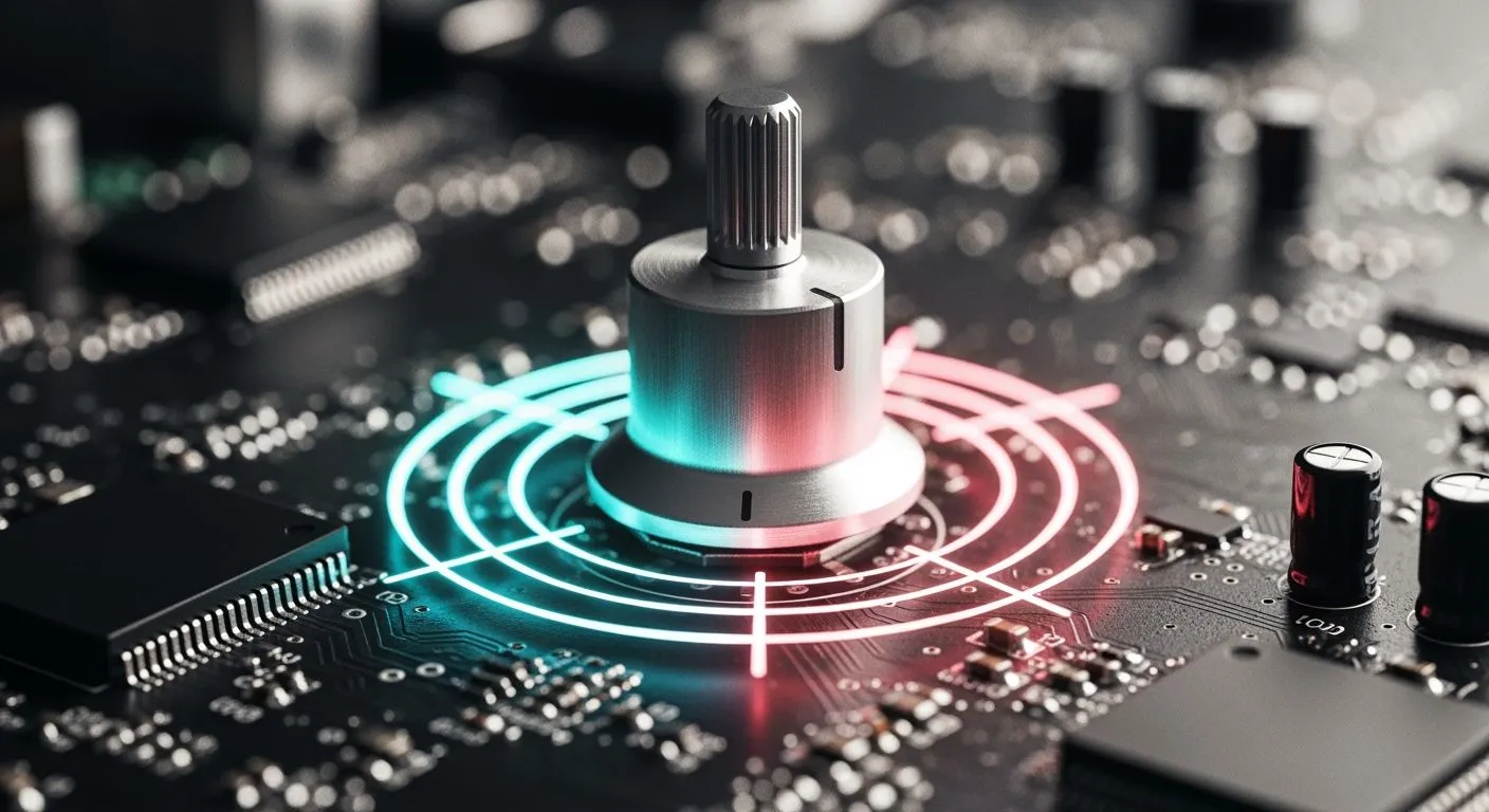
Mechanical potentiometers ruin clean audio signals in high-end systems. You face wiper bounce, contact noise, and parasitic capacitance during manual adjustments. Long panel routing constraints also invite unwanted interference into your system board. Solid-state variable resistor designs solve these problems effectively. You can replace physical wipers with remote variable resistors to keep sensitive audio signal paths short. Using a modern optoelectronic variable resister circuit isolates unwanted switching noise completely. As a HiSilicon-designated solutions partner, Nova Technology Company (HK) Limited provides advanced IC chip solutions for these challenges. Applying a steady control voltage to solid-state attenuators gives you flexible gain adjustment without mechanical wear.
Key Takeaways
- Mechanical knobs wear out over time and create noisy crackles in high-end audio systems.
- Long board wires catch unwanted electrical noise from nearby digital circuits and power supplies.
- Solid-state transistors act as variable resistors to keep audio signal paths very short.
- Optoelectronic light designs completely block switching noise and prevent annoying ground loops.
Limitations of Mechanical Audio Potentiometers
Wiper Wear and Contact Noise
Mechanical potentiometers rely on physical metal wipers sliding directly across resistive carbon tracks. Daily manual turning creates continuous friction on these delicate internal surfaces. This mechanical action quickly wears down conductive material and leaves microscopic carbon debris inside the sealed component housing. Airborne dust particles and ambient moisture also enter through tiny panel gaps over time.
These contaminated contact surfaces disrupt smooth electrical conductivity inside your signal path. You hear harsh pops, rustling sounds, and loud crackles through your speakers whenever you turn the knob. Sudden voltage jumps create annoying output noise spikes during manual adjustments. This physical degradation continuously reduces audio signal clarity and eventually causes total component failure in your gear.
Signal Routing and Parasitics
Traditional panel-mounted volume knobs force poor printed circuit board layouts. You must route delicate analog audio signals across the main board to the front panel and back again. These extended copper traces act like small antennas. They easily pick up electromagnetic interference from nearby power transformers and digital switching circuits. Integrating a modern variable resistor solves this board layout problem through remote placement, which keeps critical audio paths extremely short.
Long wiring runs also introduce unwanted parasitic cable and load capacitance into your audio path. This capacitance forms an unwanted low-pass filter with the potentiometer impedance. High-frequency audio signals suffer noticeable signal loss before reaching your power amplifier stage. The table below details typical parasitic measurement values for passive attenuator circuits:
| Parameter | Value |
|---|---|
| Cable/load capacitance | ~500 pF |
| Passive attenuator/potentiometer impedance | 15 kΩ |
| Resulting high-frequency attenuation at 20 kHz | 3 dB |
This unwanted filtering causes severe high-frequency roll-off at upper audio frequencies. You lose crisp treble detail and spatial clarity in your overall sound stage. You can eliminate these long routing loops completely by choosing modern electronic attenuation designs. Sending a steady control voltage to solid-state attenuators preserves full frequency response across all volume settings.
Solid-State Variable Resister Design with JFETs and MOSFETs
Linearized FET Voltage-Controlled Attenuators
You can operate field-effect transistors in their ohmic region to replace traditional mechanical wipers effectively. Applying a low drain-to-source voltage transforms a JFET or MOSFET into a reliable solid-state variable resister. The transistor acts as a voltage-controlled resistor for AC audio signals under these triode operating conditions. Unmodified FETs suffer from non-linear resistance changes during large signal swings in the circuit. For instance, a non-linearized JFET design shows significant visual distortion at 5 V p-p input levels. Harmonic distortion can exceed 3% for a small AC signal between -250 mV and +250 mV across the drain and source terminals. Enhancement-mode MOSFETs require a positive gate voltage to lower resistance and turn off completely at zero gate potential.
Feedback linearization techniques fix these harmonic distortion problems in solid-state audio attenuators. You can feed half of the drain voltage back to the gate terminal using resistors. This negative feedback keeps channel resistance constant across wider signal swings. A linearized JFET variable resistor maintains a steady resistance around 260 Ω for input signals from -6 V to 6 V. Push-pull topology also reduces second harmonic distortion in MOSFET circuits. As a HiSilicon-designated solutions partner, Nova Technology Company (HK) Limited provides advanced integrated circuits to streamline this analog circuit control in modern systems. Building a custom circuit stage with these specialized silicon components delivers outstanding sound purity and long-term operating reliability for high-performance audio applications.
The table below outlines performance metrics across different transistor setups:
| Device Setup | Resistance Range | Distortion Level |
|---|---|---|
| Non-linearized JFET | Rds ranges from 200 Ω to 500 Ω | High distortion at 5 V p-p |
| Linearized JFET | Rds remains constant near 260 Ω | Low distortion at 8 V p-p |
| Graded LSK489A/C | Achieves a 3:1 resistance variation | Low distortion for small signals |
Microcontroller Driven Gain Regulation
You can connect digital microcontrollers directly to your solid-state attenuator stage to manage system gain efficiently. The microcontroller uses an integrated digital-to-analog converter to generate a clean control signal for the circuit. This output changes the gate bias voltage of your remote variable resistors without any mechanical contact or friction. Sending a precise signal to a voltage-controlled resistor allows smooth audio attenuation adjustments. Microcontroller firmware updates the gate voltage dynamically to shape precise logarithmic volume curves across all listening levels.
Using solid-state voltage-controlled resistors removes all mechanical wear and wiper bounce from your audio gear. Modern microcontroller DACs deliver steady bias voltage settings to regulate a variable attenuator with high accuracy. The transistor channel operates as a dependable voltage-controlled resistor directly in the signal path. You eliminate noisy physical sliders while keeping sensitive audio traces short on your printed circuit board. Choosing a solid-state variable resistor network ensures reliable system performance over many years of continuous daily operation without signal degradation.
Optoelectronic Variable Resister Implementations in Audio
Optoelectronic circuits offer an elegant path toward clean volume adjustment. You can build an isolated design by driving an LED to illuminate a light-dependent photocell or photo-FET inside an optocoupler package. Designers often call this classic light-based element a vactrol. The internal light emitter responds directly to driver current without physical electrical contact across the audio path. This complete physical separation prevents noisy driver signals from corrupting pristine sound.
Filtered PWM Drive for Optocouplers
You can drive the LED using a high-frequency pulse-width modulation signal from your system microcontroller. Direct digital signals inject unwanted switching hash into sensitive circuits, so you must filter the drive line first. Placing a simple low-pass resistance-capacitance filter before the optical device converts digital pulses into a steady voltage level. This smooth bias voltage powers the LED evenly without high-frequency ripple.
The LED light output continuously varies the resistance of the internal photocell. This setup functions as a quiet variable resister placed directly inside your gain stage. The optical barrier creates total galvanic isolation between digital lines and delicate analog audio signals. Complete isolation eliminates ground loops completely and blocks switching hum from entering your signal path. You no longer worry about power supply ripple leaking into your speakers.
An optoelectronic variable resistor provides distinct performance benefits over direct transistor circuits. Standard voltage-controlled resistors often suffer from non-linear conduction near signal peaks. In contrast, photo-resistive elements preserve pure sine waves without adding harsh odd harmonics. Using these remote variable resistors allows you to position sensitive gain control components away from noisy front panels. You keep critical signal lines short while running DC lines anywhere inside your equipment enclosure.
Achieving Logarithmic Attenuation Response
Human ears perceive sound intensity on a logarithmic scale. Linear adjustments make volume sweeps feel abrupt at low levels and sluggish near maximum power. You must convert linear digital tuning steps into a logarithmic response curve to achieve natural volume changes.
A standard microcontroller lookup table maps linear PWM duty cycles to precise exponential voltage outputs. The LED converts this shaped voltage into proportional light output. The internal photocell then operates as a true voltage-controlled resistor with logarithmic attenuation characteristics. You enjoy steady attenuation steps that match human auditory perception perfectly.
| Gain Step | PWM Duty Cycle | Photocell Resistance | Attenuation Level |
|---|---|---|---|
| Step 1 | 5% | 100 kΩ | -60 dB |
| Step 2 | 25% | 10 kΩ | -40 dB |
| Step 3 | 60% | 1 kΩ | -20 dB |
| Step 4 | 100% | 100 Ω | 0 dB |
This precise mapping creates smooth audio transitions across the entire volume range. The optical vactrol element maintains continuous contact-free operation without sudden noise jumps. A modern variable resistor setup maintains consistent response across all listening levels. You also achieve precise logarithmic tracking between channels in stereo audio configurations.
Combining optical isolation with digital control gives you a resilient variable attenuator for premium audio gear. The optical element replaces traditional mechanical wipers while protecting sensitive audio stages from digital voltage spikes. This stable bias voltage technique creates reliable circuits for studio consoles, high-end preamplifiers, and automotive systems. Professional sound systems maintain exceptional audio transparency across decades of continuous operation.
Circuit Testing and Layout Best Practices
THD+N and Frequency Response Performance
You must measure total harmonic distortion plus noise across the full audible spectrum during testing. Bench tests confirm that solid-state attenuators maintain pristine audio clarity across all volume steps. Direct signal paths prevent unwanted high-frequency roll-off. You achieve flat frequency response when you eliminate long routing cables.
Proper bias voltage stability protects your audio circuit from unwanted distortion spikes. High input levels can shift field-effect transistor channels into non-linear operation. You can feed half of the output audio signal back into the gate terminal. This negative feedback stabilizes channel resistance during peak signal swings. Continuous bias voltage tracking keeps total harmonic distortion extremely low across every listening level.
Minimizing Control Line Noise Injection
Digital switching circuits can easily inject unwanted clock noise into your analog audio path. You must isolate your digital control lines from sensitive analog traces. Using optocouplers galvanically isolates the digital system from your audio attenuator stage. This physical separation prevents ground loops completely. You can also run differential signaling to reject common-mode noise along long runs.
Good printed circuit board layout decisions protect your signal integrity. The table below outlines key layout practices for mixed-signal attenuator board designs:
| Rule | Noise-reduction mechanism |
|---|---|
| Continuous ground plane under signal traces | Maintains a low-inductance return path and minimizes ground-loop noise. |
| Star power routing | Prevents parasitic inductance and unintended circuit feedback. |
| Ground-stitching vias near sensitive traces | Confines return fields and reduces coupling from adjacent control traces. |
You should route high-speed digital lines on separate board layers away from analog traces. Placing bypass capacitors close to power pins provides short return paths to ground. A stable supply voltage keeps digital ripple out of your sensitive analog bias circuits. Adjusting your target voltage dynamically maintains low distortion across all volume settings. Following these layout techniques guarantees ultra-quiet operation for high-performance sound systems.
Mechanical knobs wear out quickly and add severe contact noise to your system. Selecting a FET as a voltage-controlled resistor provides low system cost and fast response. However, large signals cause noticeable distortion without feedback control. Using an optoelectronic variable resister gives you complete electrical isolation and zero switching hum, but it costs more.
You can pick the best design for your specific project. Choose a JFET variable resistor for budget-sensitive smart home devices. Optoelectronic designs work best in high-end professional audio gear where complete isolation is critical. Automotive equipment benefits from solid-state drive circuits that resist vehicle vibrations and mechanical stress.
FAQ
Why should you replace mechanical potentiometers in audio designs?
Mechanical potentiometers wear out over time. Sliding wipers create carbon dust, rustling noise, and sudden signal crackles. Long wiring runs to front panels also invite unwanted interference. Modern solid-state options keep your audio paths short and clean.
How does a FET act as a variable resistor?
You operate a FET in its ohmic region using a specific bias voltage across the gate. The transistor channel then acts like a resistor. Applying negative feedback prevents distortion during large audio signal swings.
What makes optoelectronic attenuators better for high-end audio?
Optoelectronic designs use internal LEDs and light-sensitive cells to provide total physical separation. This optical barrier stops ground loops and blocks switching hum completely. You get ultra-quiet volume control without introducing digital noise into your analog signal path.
How do you get a smooth logarithmic volume curve using digital signals?
Human ears hear sound logarithmically. Microcontrollers map linear digital steps to exponential output curves using internal lookup tables. This mapping drives the attenuator smoothly, creating natural volume changes across every listening level.