Real-World Applications of the IRF540 Power MOSFET: Case Studies and Insights
Expert guide on Real-World Applications of the IRF540 Power MOSFET: Case Studies and Insights. Technical specs, applications, sourcing tips for engineers and buyers.
Introduction
In the evolving landscape of electronics, the IRF540 Power MOSFET stands out as a versatile component pivotal in numerous applications. This power MOSFET is renowned for its ability to handle substantial power levels, making it a staple in industries ranging from automotive to consumer electronics. As global semiconductor revenue is projected to reach $595.2 billion by 2026, the demand for reliable components like the IRF540 Power MOSFET continues to surge. This article delves into its technical specifications, real-world applications, and offers a comprehensive guide for engineers and hobbyists alike.
Technical Overview
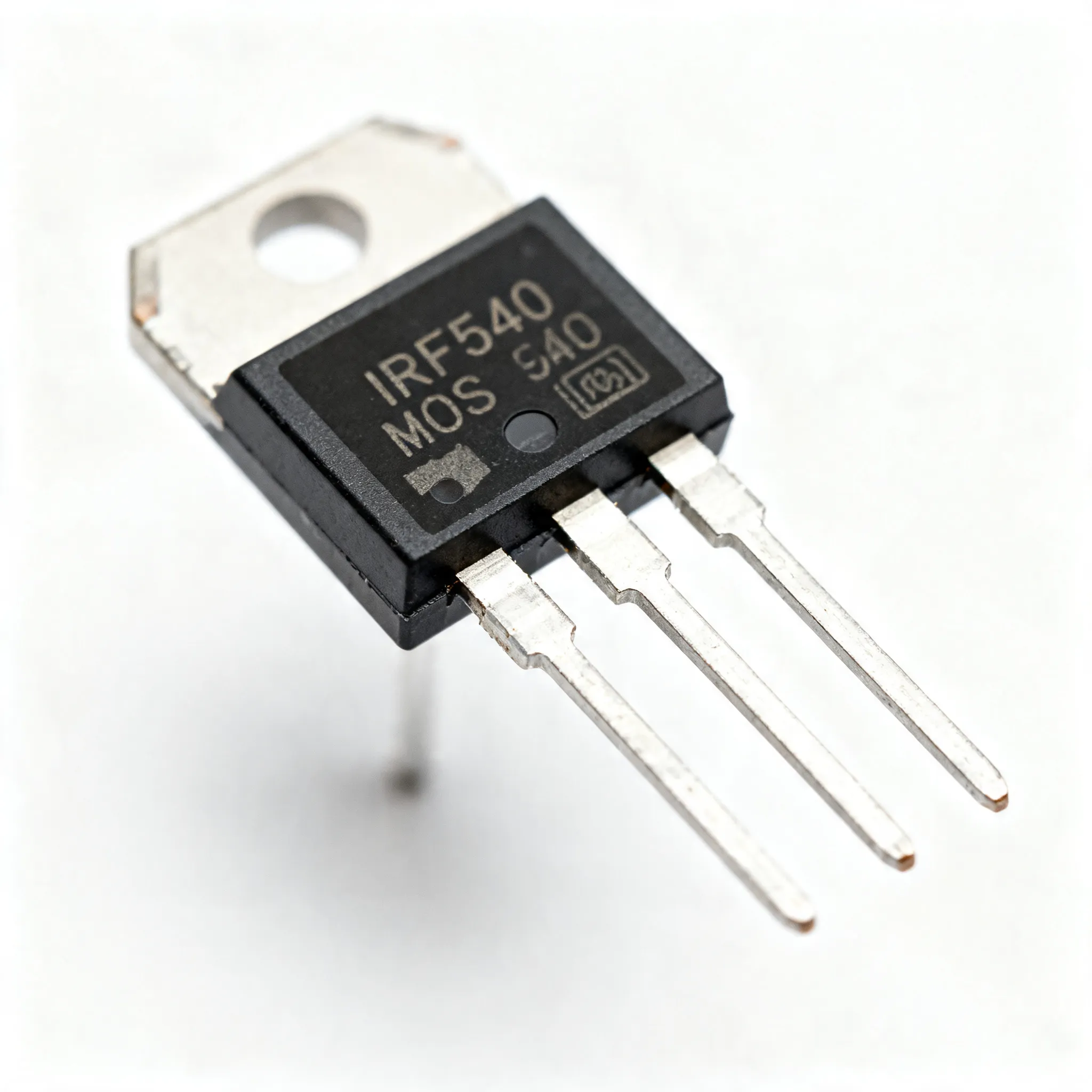
The IRF540 Power MOSFET is a type of metal-oxide-semiconductor field-effect transistor (MOSFET) that functions primarily as an electronic switch or amplifier in various circuits. Its ability to handle high voltages and currents makes it essential in power management applications. The core concept of a MOSFET revolves around its three terminals: the gate, drain, and source. The IRF540 Power MOSFET specifically is designed to operate efficiently with a gate-source voltage of 10V, enabling it to handle a continuous drain current of up to 28A. The low on-resistance of 0.077 ohms ensures minimal power loss, enhancing efficiency in electronic designs.
Additionally, the IRF540 Power MOSFET exhibits rapid switching capabilities due to its low gate charge, making it suitable for high-speed applications. Its construction allows for efficient thermal management, ensuring stability even under extreme conditions. In essence, the IRF540 Power MOSFET is a robust component that balances performance with reliability, a key factor in today's demanding electronic environments.
Detailed Specifications
| Parameter | Value | Units | Notes |
|---|---|---|---|
| Drain-Source Voltage (VDS) | 100 | V | Maximum voltage between drain and source |
| Continuous Drain Current (ID) | 28 | A | At 25°C, free air |
| Pulsed Drain Current (IDM) | 110 | A | Pulsed current capability |
| Gate-Source Voltage (VGS) | ±20 | V | Maximum voltage between gate and source |
| Gate Threshold Voltage (VGS(th)) | 2.0 - 4.0 | V | Threshold voltage range |
| On-State Resistance (RDS(on)) | 0.077 | Ω | Typical resistance when fully on |
| Power Dissipation (PD) | 150 | W | Maximum power dissipation |
| Input Capacitance (Ciss) | 1350 | pF | Capacitance between gate and source |
| Output Capacitance (Coss) | 350 | pF | Capacitance between drain and source |
| Reverse Transfer Capacitance (Crss) | 75 | pF | Capacitance between gate and drain |
| Parameter | Value | Units | Notes |
|---|---|---|---|
| Junction-to-Ambient Thermal Resistance (RθJA) | 62.5 | °C/W | Without heat sink |
| Junction-to-Case Thermal Resistance (RθJC) | 1.0 | °C/W | With heat sink |
| Operating Junction Temperature (TJ) | -55 to 175 | °C | Operating temperature range |
| Storage Temperature (Tstg) | -55 to 175 | °C | Storage temperature range |
| Package Type | TO-220 | - | Standard package for power MOSFETs |
| Mounting Style | Through Hole | - | For PCB mounting |
| Lead-Free | Yes | - | Complies with RoHS |
| Weight | 1.9 | g | Typical mass of the component |
| Application | Benefits | Challenges | Notes |
|---|---|---|---|
| Switch Mode Power Supplies (SMPS) | High efficiency, fast switching | Thermal management required | Common in consumer electronics |
| Motor Control | High current handling, durability | Requires precise PWM control | Used in automotive applications |
| Audio Amplifiers | Low distortion, high power output | Complexity in circuit design | Utilized in high-fidelity audio systems |
| Lighting Systems | Energy efficient, long lifespan | Initial cost can be high | LED and fluorescent lamps |
| Solar Inverters | Renewable energy integration | Efficiency drops at high temperature | Key in solar panel systems |
Design Considerations
When integrating the IRF540 Power MOSFET into a design, several critical factors must be considered to optimize performance and reliability. First and foremost is the thermal management. Given the power dissipation capabilities of the IRF540 Power MOSFET, adequate heat sinking and possibly active cooling are necessary to maintain junction temperatures within safe limits. This is particularly crucial in high-power applications where prolonged operation can lead to thermal runaway if not properly managed.
Another key consideration is the gate drive voltage. The IRF540 Power MOSFET requires a gate-source voltage of approximately 10V for optimal operation, ensuring the MOSFET is fully turned on and the on-state resistance is minimized. Designers should ensure that the gate driver circuit can supply this voltage reliably, even under varying load conditions.
The switching speed is another critical parameter. While the IRF540 Power MOSFET is capable of fast switching, the actual speed in a circuit is influenced by the gate charge and the driver circuit's ability to supply and sink current. Careful selection of gate resistors and consideration of parasitic inductances can significantly impact the switching performance.
Additionally, circuit designers should consider the maximum allowable drain-source voltage and current ratings to avoid breakdown. The IRF540 Power MOSFET has a maximum VDS of 100V and a continuous drain current of 28A. Exceeding these limits can result in device failure. Protective circuits such as clamping diodes and current limiters are advisable to safeguard against transient spikes and overcurrent conditions.
Step-by-Step Guide
Implementing the IRF540 Power MOSFET into a circuit can be streamlined with a methodical approach. Here’s a step-by-step guide:
- Understand Application Requirements: Determine the voltage, current, and power requirements of your application. Ensure the IRF540 Power MOSFET meets these specifications, considering safety margins.
- Design the Gate Drive Circuit: Use a gate driver capable of supplying the necessary voltage and current to switch the MOSFET efficiently. Consider the use of low-value gate resistors to minimize switching loss.
- Plan for Thermal Management: Design a thermal management solution that includes heat sinks and possibly fans. Calculate the expected power dissipation and ensure your cooling solution can maintain safe operating temperatures.
- Incorporate Protection Mechanisms: Implement overvoltage, overcurrent, and thermal protection circuits. This could include TVS diodes, fuses, and thermal shutdown mechanisms.
- Layout the PCB: Pay attention to trace widths and lengths to handle the high currents efficiently. Minimize parasitic inductances and ensure good thermal and electrical connections.
- Assemble and Test the Prototype: Once the PCB is manufactured, assemble the components and perform initial testing. Verify the gate drive voltage, switching speeds, and thermal performance under load.
- Optimize and Iterate: Based on test results, make necessary adjustments. This could involve tweaking the gate drive circuit, enhancing thermal management, or adjusting component values for improved performance.
- Finalize Design for Production: After successful testing and optimization, prepare the design for mass production. Ensure all components are readily available and the design meets all regulatory requirements.
Common Issues & Solutions
While the IRF540 Power MOSFET is a robust component, several common issues can arise during its application:
- Overheating: A common issue due to inadequate thermal management. Solution: Use larger heat sinks or active cooling methods to dissipate heat effectively.
- Gate Drive Problems: Inadequate gate voltage can prevent the MOSFET from fully turning on. Solution: Ensure the gate driver circuit can supply the required voltage and current.
- Parasitic Oscillations: Fast switching can lead to unwanted oscillations. Solution: Use gate resistors and snubber circuits to dampen high-frequency oscillations.
- Overcurrent Conditions: Excessive current can damage the MOSFET. Solution: Implement current limiting circuits and use fuses to protect against overcurrent.
- Voltage Spikes: Transient voltage spikes can exceed the VDS rating. Solution: Use clamping diodes or TVS diodes to protect against voltage transients.
Applications & Use Cases
The IRF540 Power MOSFET finds applications in a wide range of industries due to its robust performance. In automotive systems, it's commonly used in motor controls for electric vehicles and hybrid systems. Its high current handling and fast switching capabilities make it ideal for these applications.
In consumer electronics, the IRF540 Power MOSFET is often utilized in switch-mode power supplies (SMPS), providing efficient power conversion with minimal loss. Additionally, it's employed in audio amplifier circuits, delivering high power output with low distortion, a crucial factor in high-fidelity audio systems.
Moreover, the IRF540 Power MOSFET is integral to renewable energy systems, particularly in solar inverters, where it helps in converting DC to AC power efficiently. Its role in lighting systems, especially LED drivers, underscores its versatility in energy-efficient applications.
Selection & Sourcing Guide
Selecting the right IRF540 Power MOSFET for your application involves considering the electrical and thermal specifications relative to your design requirements. It's crucial to source components from reputable distributors to ensure quality and authenticity. For competitive pricing and reliable sourcing, consider using authorized distributors like IC Online. They offer a wide range of electronic components with fast delivery options.
FAQ
- Q: What is the maximum voltage the IRF540 Power MOSFET can handle?
A: The maximum drain-source voltage (VDS) is 100V. - Q: Can the IRF540 Power MOSFET be used in high-frequency applications?
A: Yes, its fast switching capabilities make it suitable for high-frequency applications. - Q: What type of package does the IRF540 Power MOSFET come in?
A: It is typically available in a TO-220 package. - Q: How do I ensure proper thermal management for the IRF540 Power MOSFET?
A: Use adequate heat sinking and possibly active cooling methods to dissipate heat. - Q: Is the IRF540 Power MOSFET RoHS compliant?
A: Yes, it is lead-free and complies with RoHS standards. - Q: Can the IRF540 Power MOSFET handle pulsed currents?
A: Yes, it can handle pulsed drain currents up to 110A. - Q: What are common applications for the IRF540 Power MOSFET?
A: Common applications include SMPS, motor control, audio amplifiers, and solar inverters. - Q: What is the gate-source voltage requirement for the IRF540 Power MOSFET?
A: The gate-source voltage should be approximately 10V for optimal operation.
Conclusion
The IRF540 Power MOSFET is a cornerstone in modern electronic design, offering a blend of high performance, reliability, and versatility. Whether in power supplies, motor controls, or renewable energy systems, its role is indispensable. Understanding its specifications and proper integration techniques is crucial for harnessing its full potential. As the demand for efficient power management continues to rise, the IRF540 Power MOSFET remains a vital component in the toolkit of engineers and designers worldwide.