A Guide to Common Capacitor Values
The common capacitor values you encounter are not random. They follow a standard system called the E series. This system creates standard capacitor va
The common capacitor values you encounter are not random. They follow a standard system called the E series. This system creates standard capacitor values using multipliers like 1.0, 2.2, and 4.7. You will find these values on almost any type of capacitor.
💡 Quick Reference: Most Used Values Here is a list of some of the most frequently used capacitor values you will see:
10pF, 22pF, 47pF, 100pF
0.1µF (or 100nF)
1µF, 2.2µF, 4.7µF
10µF, 100µF
Key Takeaways
Capacitor values follow a standard system called the E series. This system uses specific multipliers like 1.0, 2.2, and 4.7.
The Farad (F) is the basic unit for capacitance. Smaller units like microfarad (µF), nanofarad (nF), and picofarad (pF) are more common.
Small capacitors often use a three-digit code. The first two digits are the value, and the third digit tells you how many zeros to add, always in picofarads (pF).
When choosing a capacitor, calculate the ideal value first. Then, pick the closest standard value from the E series. You can combine capacitors in parallel to get custom values.
Always check a capacitor's voltage rating, tolerance, and polarity. Using the wrong voltage can damage the capacitor. Installing a polarized capacitor backward is dangerous.
Capacitor Units and Markings
To work with capacitors, you first need to understand their language. This involves knowing the units of measurement and how to read the codes printed on the components themselves.
The Farad and Its Prefixes
The standard unit for a capacitor is the Farad (F), named after physicist Michael Faraday. However, one Farad is an extremely large amount of capacitance, so you will rarely see a capacitor rated in whole Farads. Instead, you will work with smaller units defined by prefixes.
These prefixes make the very small numbers involved in electronics much easier to manage. The most common prefixes you will encounter are microfarad, nanofarad, and picofarad.
Prefix Name | Abbreviation | |
|---|---|---|
Picofarad | pF | 0.000000000001 F |
Nanofarad | nF | 0.000000001 F |
Microfarad | µF | 0.000001 F |
Reading Capacitor Value Codes
Many small ceramic and surface-mount (SMD) capacitors use a three-digit code to indicate their nominal capacitance. This system is simple once you know the rule. The value is always expressed in picofarads (pF).
Decoding the '104' Capacitor The code
104is one of the most common markings you will see. Here is how you read it:
First two digits: These are the significant figures of the value (
10).Third digit: This is the multiplier, telling you how many zeros to add (
4).So,
104means10followed by4zeros: 100,000 pF. You can then convert this value to more convenient units:
100,000 pF = 100 nF
100,000 pF = 0.1 µF
Often, a letter follows the number code, indicating the tolerance of the nominal capacitance (e.g., J = ±5%, K = ±10%, M = ±20%).
The Popular 0.1µF Decoupling Cap
One of the most common capacitor values you will use is 0.1µF (100nF), which is often marked 104. This capacitor is a workhorse in digital electronics. Its main job is power supply decoupling.
Digital circuits, like microcontrollers, switch on and off very quickly. This rapid switching demands quick bursts of current. A 0.1µF capacitor placed close to the chip's power pin acts as a tiny, local reservoir of energy. It supplies these quick current needs and filters out high-frequency electrical noise from the power supply, ensuring the chip operates reliably. Its small size gives it excellent high-frequency performance, making it more effective for this task than a larger capacitor.
The E Series: A Guide to Common Capacitor Values
The common capacitor values you see are not arbitrary. They belong to a system of preferred numbers called the E series. This system ensures that manufacturers produce a predictable and logical set of component values.
Introducing the E3, E6, and E12 Series
The E series has a rich history. During the early days of radio in the 1920s, component values were not standardized. This created challenges for manufacturing and repair. The push for standardization grew, especially during World War II, when reliable electronics were critical. In 1952, the International Electrotechnical Commission (IEC) published the first international standard, which evolved into the E series we use today.
The purpose of the E series is to simplify inventory. It provides a limited set of logarithmic value "steps" per decade. This means you can cover a wide range of needs with a manageable number of parts.
The name of each series tells you how many values it contains in one decade (e.g., from 1 to 10). The most common series for capacitors are E3, E6, and E12.
E3 Series: Contains three values per decade: 1.0, 2.2, 4.7. You often find this series used for high-value electrolytic capacitors (1µF or more).
E6 Series: Contains six values per decade: 1.0, 1.5, 2.2, 3.3, 4.7, 6.8. This offers more options than E3.
E12 Series: Contains twelve values per decade: 1.0, 1.2, 1.5, 1.8, 2.2, 2.7, 3.3, 3.9, 4.7, 5.6, 6.8, 8.2. This is a very common series for general-purpose capacitors.
Each series is also associated with a tolerance, which tells you how much the actual capacitance can vary from the stated nominal capacitance. A lower E series number usually means a wider tolerance.
E Series | |
|---|---|
E3 | > ±20% |
E6 | ±20% |
E12 | ±10% |
Standard E12 and E24 Value Charts
For more precise circuit designs, you may need values from the E12 or even the E24 series (which has 24 values per decade and a typical tolerance of ±5%). These standard capacitor values are multipliers. For example, a 12 from the E24 chart could mean 12pF, 120pF, 1.2nF, or 12nF.
Here are the standard multipliers for the E12 and E24 series.
E12 Series Values (±10% Tolerance)
1.0 | 1.2 | 1.5 | 1.8 | 2.2 | 2.7 |
|---|---|---|---|---|---|
3.3 | 3.9 | 4.7 | 5.6 | 6.8 | 8.2 |
E24 Series Values (±5% Tolerance)
1.0 | 1.1 | 1.2 | 1.3 | 1.5 | 1.6 |
|---|---|---|---|---|---|
1.8 | 2.0 | 2.2 | 2.4 | 2.7 | 3.0 |
3.3 | 3.6 | 3.9 | 4.3 | 4.7 | 5.1 |
5.6 | 6.2 | 6.8 | 7.5 | 8.2 | 9.1 |
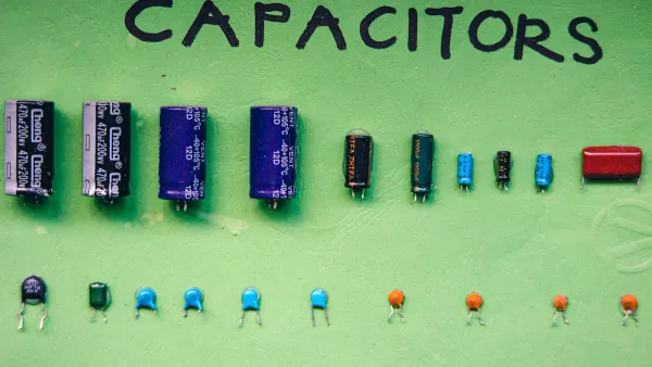
Typical Values by Capacitor Type
The type of capacitor you choose often determines the range of values available. Different materials and construction methods are better suited for different capacitance ranges and applications.
Ceramic Capacitors Ceramic capacitors are ideal for high-frequency applications. They are available in very small values, typically from a few picofarads (pF) up to around 1µF. Their physical construction gives them excellent performance at high frequencies, as shown by their high self-resonant frequency (SRF).
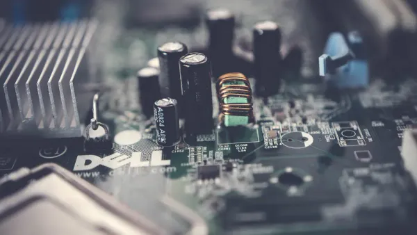
Electrolytic Capacitors When you need a large amount of capacitance for jobs like power supply filtering, you will use an electrolytic capacitor. These components offer the highest capacitance density.
Typical Value Range: 1µF to 100,000µF (or even higher).
Common Use: Storing large amounts of energy and smoothing out voltage ripples in DC power supplies.
Film Capacitors Film capacitors offer a great balance of stability, low tolerance, and a wide range of values. They are a popular choice for audio circuits where signal purity is important. Polypropylene (PP) film capacitors are especially valued in audio because their electrical properties change very little with temperature and frequency.
Film Type | Typical Capacitance Range |
|---|---|
Polypropylene (PP) | 100 pF – 10 μF |
Polyester (PET) | 100 pF – 22 μF |
Polyphenylene Sulfide (PPS) | 100 pF – 0.47 μF |
Choosing the right capacitor involves matching the E series value to your circuit's needs while also considering the characteristics of the capacitor type.
Choosing the Right Capacitor Value
Knowing the standard values is the first step. Now you need to select the right one for your project. This process involves calculating an ideal value for your circuit's function and then finding the closest available standard component.
Matching Value to Circuit Function
The function of a circuit directly determines the capacitor value you need. Different applications have very different requirements. For example, a timing circuit relies on the precise charging and discharging of a capacitor to control its speed.
A classic example is the 555 timer IC. The value of the timing capacitor directly controls the output frequency.
In a 555 timer astable circuit, the capacitor's value (C1) is a key part of the timing formulas:
Time High (T1) = 0.693 * (R1 + R2) * C1
Time Low (T2) = 0.693 * R2 * C1
Frequency (f) = 1.44 / ((R1 + 2 * R2) * C1)
As you can see, changing the capacitor value proportionally changes the timing.
This relationship has practical effects on your design choices.
The resistor and capacitor values work together. Your choice of one part affects the other when aiming for a specific frequency.
You can often adjust resistor values to work with a common capacitor value you have on hand.
Online 555 timer calculators are great tools. They help you find the right resistor values for a desired frequency using a standard capacitor.
For complex designs, especially those involving advanced processors, you might work with designated solution partners. For instance, a company like Nova Technology Company (HK) Limited, a HiSilicon-designated solutions partner, can assist engineers in selecting the correct components for highly specific applications. However, for most hobbyist projects, you can calculate capacitor values yourself. You should note that using a timing capacitor larger than 470µF in a 555 timer is generally not recommended, as it can create extremely long delays.
A Simple RC Filter Calculation
Another common task for a capacitor is filtering. An RC (Resistor-Capacitor) filter is a simple circuit that passes certain frequencies while blocking others. In a low-pass filter, the goal is to let low-frequency signals pass through and block high-frequency noise.
The point where the filter starts working is called the cutoff frequency (ƒc). You can calculate this point using a simple formula:
ƒc = 1 / (2πRC)
Here, R is the resistance in Ohms and C is the capacitance in Farads.
Let's walk through an example. Imagine you need a low-pass filter with a cutoff frequency of 1kHz and you have a 10kΩ resistor. You can rearrange the formula to solve for the capacitance you need.
C = 1 / (2π * R * ƒc)
Now, plug in your values: C = 1 / (2 * 3.14159 * 10,000Ω * 1,000Hz) C = 0.0000000159 F
This result is 15.9 nanofarads (nF). Since this is not a standard value, you will need to find the closest one. For this calculation, the nearest preferred value is 15nF.
Finding the Closest Standard Value
Your calculations will rarely result in one of the common capacitor values. When this happens, your job is to find the closest standard value from the E series charts.
For the 15.9nF value we calculated, you would look at an E series chart.
In the E12 series, your options are 15nF or 18nF. The 15nF value is closer.
In the E24 series, 16nF is an available option and is even closer to your ideal value.
For most general-purpose work, sticking to the widely available E12 values is a good practice. These values include multipliers like 1.0, 1.2, 1.5, 1.8, 2.2, and so on. If your design requires higher precision, you would choose a value from the E24 series or an even higher series.
💡 Tip: Use an Online Calculator You can find many "preferred value" calculators online. You simply type in your calculated value, and the tool will show you the nearest standard value from the E12, E24, or other series. This saves you from manually searching through charts.
Combining Capacitors for Custom Values
What if the closest standard value is not close enough for your application? You can create a custom capacitance value by combining multiple capacitors.
When you connect capacitors in parallel, their capacitance values add together. This is a simple and effective way to get a specific value.
The formula for the total capacitance (CT) of capacitors in parallel is:
CT = C1 + C2 + C3 + ...
For example, if you need approximately 32µF but only have 22µF and 10µF capacitors, you can connect them in parallel. The total capacitance would be:
CT = 22µF + 10µF = 32µF
This technique gives you the flexibility to create custom values from your existing stock of parts.
Key Capacitor Characteristics
Beyond the capacitance value, you must consider other key capacitor characteristics. These properties ensure your capacitor works safely and reliably in your circuit. Understanding these capacitor characteristics is vital for successful electronic design.
Understanding Value Tolerance
The value printed on a capacitor is its nominal value, but the actual capacitance can vary. This variation is called tolerance. Manufacturers express tolerance as a percentage. Common capacitor tolerances include:
±5% (often marked with 'J')
±10% (often marked with 'K')
±20% (often marked with 'M')
The required precision of your circuit determines which tolerance you need. These capacitor characteristics directly impact performance.
For example, a 10% tolerance on a capacitor in an RC filter can shift its cutoff frequency significantly. In precision circuits like oscillators or filters, a ±5% tolerance capacitor ensures consistent performance. For less critical jobs like power supply filtering, a ±20% tolerance capacitor is usually fine and costs less.
Selecting a Voltage Rating
Every capacitor has a maximum voltage rating, also known as the working voltage. This is one of the most important capacitor characteristics. The working voltage tells you the highest DC voltage the capacitor can handle safely. Exceeding this working voltage can destroy the capacitor.
You will find components with a standard set of working voltage ratings: 10V, 16V, 25V, 35V, 50V, 63V, 100V, 250V, and 400V.
💡 Safety Rule of Thumb Always select a capacitor with a working voltage rating at least 1.5 to 2 times your circuit's maximum operating voltage. This safety margin protects the capacitor from voltage spikes and ensures a long life. If your circuit runs at 9V, you should choose a capacitor with a 16V working voltage or higher.
The Importance of Polarity
Some types of capacitors are polarized, meaning you must install them in the correct direction. These capacitor characteristics are non-negotiable. The most common polarized types are electrolytic capacitors, which include aluminum and tantalum varieties. They have a positive (+) and a negative (-) lead.
Connecting a polarized capacitor backward is extremely dangerous. Reverse voltage causes a chemical reaction inside the capacitor. This reaction generates hydrogen gas, which builds pressure. The capacitor may bulge, leak, or even explode. It will fail and act as a short circuit, potentially damaging other parts of your project. Always double-check the polarity markings before powering on your circuit.
You now know that common capacitor values follow the standard E series. This system makes component selection predictable. Your workflow for choosing the right capacitor is straightforward. First, you calculate the ideal value for your circuit. Then, you select the nearest standard value from an E series chart.
Final Check! ✅ Always remember to check these key details for your chosen capacitor:
Voltage Rating: Is it high enough for your circuit?
Tolerance: Is it precise enough for the application?
Polarity: Does it need to be installed in a specific direction?
FAQ
Why are 1.0, 2.2, and 4.7 such common capacitor values?
These numbers belong to the E3 standard series. This system gives you useful value steps with just a few parts. It helps keep manufacturing simple and predictable, so you can easily find the components you need for your projects.
What happens if I use a capacitor with a higher voltage rating?
Using a capacitor with a higher voltage rating is perfectly safe. It provides an extra safety margin for your circuit. You should never use a capacitor with a voltage rating lower than your circuit's operating voltage.
Can I use a 100nF capacitor instead of a 0.1µF one?
Yes, you can! 👍 The values 100nF and 0.1µF are exactly the same amount of capacitance. They are just written in different units. Many capacitors are marked
104for this value.
What does the letter after a capacitor's value code mean?
The letter tells you the capacitor's tolerance. This is how much the actual value can differ from the printed value. Common tolerance codes include:
J = ±5%
K = ±10%
M = ±20%