A Guide to Critical Component RF Specification
Understanding component rf specifications helps engineers make good RF systems. Each RF component type has its own job in communication today.
Understanding component rf specifications helps engineers make good RF systems. Each RF component type has its own job in communication today. The table below lists some common RF components and what they do:
|
RF Component Type |
Examples |
Role in Modern Communication Systems |
|---|---|---|
|
Passive Components |
Shape and steady RF signals, match impedance, block bad frequencies, and help tune circuits. |
|
|
Active Components |
Power Amplifiers, Mixers, Transceivers |
Make signals stronger, change frequencies, and let two-way communication happen. |
|
Antennas & Tuners |
Dipole, Patch Antennas, Antenna Tuners |
Send and get signals, help match impedance for better power transfer. |
|
Connectors & Cables |
SMA, BNC, Coaxial cables |
Keep signals strong by lowering loss and making sure parts connect well. |
Picking the right component rf specifications makes sure all parts work together for the best system.
Key Takeaways
-
Pick RF components that work in the right frequency range. This helps stop signal loss and distortion. Match impedance between parts for strong power transfer. This also lowers signal reflection. Choose parts with power handling ratings higher than you need. This keeps them safe and working well. Use low noise figure components to find weak signals. This makes the receiver more sensitive. Pick parts with good linearity to stop signal distortion. This keeps communication clear.
Key Component RF Specifications
Frequency Range
Frequency range tells us the group of frequencies a component can use. Each part, like a power amplifier or phase-locked loop, has its own frequency range. This range shows where the part works best in a system.
-
A voltage-controlled oscillator might work from 1 GHz to 2 GHz. This makes it good for some wireless bands.
-
A frequency synthesizer needs a big frequency range to use many channels.
Tip: Always look at the frequency range of each part. Make sure it fits the system’s band. If you use a part outside its range, you might lose signal or get distortion.
Impedance
Impedance shows how much a part stops current at a certain frequency. Most RF systems use 50 ohms for best power transfer and less signal reflection.
If two parts do not have the same impedance, problems can happen:
-
Power transfer between source and load goes down.
-
Reflections can cause signal loss and distortion.
Some ways to match impedance are:
-
Use L networks with inductors and capacitors to fix reactance and change impedances.
-
Use T networks, which are two L networks together, to control the quality factor (Q).
-
Change series and parallel reactances to make a virtual resistor that matches the source.
-
Check and improve matching networks with simulation tools.
Note: Matching impedance is very important for all RF parts, like cables, switches, and amplifiers. For example, a low-noise amplifier with bad impedance matching can lose sensitivity. A power amplifier may not give full output.
Power Handling
Power handling tells us how much power a part can take without breaking or losing performance. This is important for power amplifiers, switches, and connectors.
There are two types of power handling:
-
Average power handling: The amount of power a part can take for a long time. This is limited by heat and material strength.
-
Peak power handling: The most power a part can take for a short time before it breaks down.
Most failures happen at connectors or where parts join, not inside the circuit. The highest power handling is usually set by these spots.
|
Directional Coupler Type |
|
|---|---|
|
Stripline Directional Coupler |
20 - 100 W |
|
Stripline Dual Directional Coupler |
20 - 100 W |
|
Airline Directional Coupler |
15 - 500 W |
|
High Power Stripline Directional Coupler |
60 - 200 W |
|
High Directivity Bridge Coupler |
~1 W |
The power handling of RF switches and connectors depends on many things:
-
Switch type (mechanical switches can take more power than solid-state switches).
-
Power rating and how well it gets rid of heat.
-
How strong it is against weather and other conditions.
-
Design features like cooling and tough cases.
A power amplifier in a transmitter might need to handle hundreds of watts. A low-noise amplifier at the receiver only handles milliwatts.
Tip: Always pick parts with power handling ratings higher than what you need. Think about the environment and connector quality too.
Noise Figure
Noise figure (NF) tells us how much noise a part adds to a signal. This is very important for receivers and low-noise amplifiers. A lower noise figure means less noise is added, so the system can find weak signals better.
-
The noise floor is the lowest signal the receiver can find.
-
A low noise figure helps the system pick up weak signals.
-
Outside noise and antenna quality also matter, but noise figure is still key.
|
Device Type |
Application / Description |
|
|---|---|---|
|
Low-Noise Amplifiers (LNAs) |
GPS/GNSS LNA |
~0.88 dB |
|
LNAs |
WLAN LNA |
~1.1 dB |
|
LNAs |
Broadband Gain Block |
~2.1 dB |
|
Mixers |
Ideal noiseless mixer (SSB NF) |
~3 dB |
|
Mixers |
Practical mixers |
Typically ≥ 3 dB |
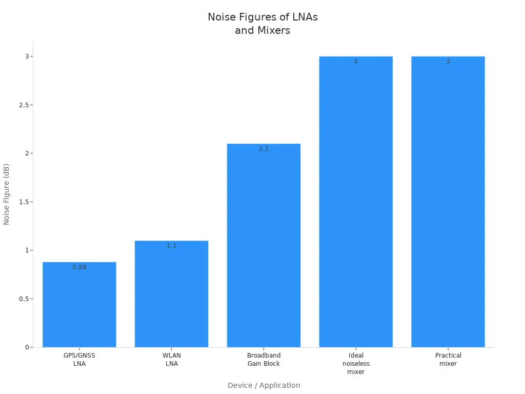
A low-noise amplifier usually has a noise figure under 2 dB. Mixers often have higher noise figures. Putting a low-noise amplifier before a mixer helps keep the total noise figure low.
Linearity
Linearity tells us how well a part, like a power amplifier or mixer, keeps the input and output signals in a straight line. If it is not linear, you get distortion and unwanted signals.
Two common linearity specs are:
|
Specification |
Definition |
Operational Meaning |
Effect on System Performance |
|---|---|---|---|
|
Input power level where amplifier gain drops by 1 dB from linear gain |
Shows when the amplifier starts to compress and act non-linear |
Working below this point stops distortion and keeps signals clear |
|
|
IP3 (Third-Order Intercept Point) |
Theoretical point where third-order intermodulation distortion equals main signal strength |
Shows how well the amplifier avoids making unwanted signals; this point is never reached in real life |
Higher IP3 means better linearity and less unwanted signals, so it can handle bigger signals without problems |
-
P1dB shows when an amplifier starts to compress and distort.
-
IP3 shows how well a part avoids making extra signals.
Tip: For systems like cellular or Wi-Fi, pick parts with high P1dB and IP3. This helps stop signal distortion.
Bandwidth
Bandwidth is the group of frequencies a part can use with little loss. It is often set by the -3 dB points, where the signal drops to half power.
-
Channel bandwidth is the range a channel can use with little loss.
-
Signal bandwidth is the range of the signal itself.
-
Data rate depends on bandwidth. Faster data needs more bandwidth.
-
The Nyquist frequency sets the smallest channel bandwidth for a certain data rate.
A power amplifier or low-noise amplifier with wide bandwidth can work with many standards. A phase-locked loop or frequency synthesizer also needs enough bandwidth to lock onto signals fast and right.
-
PCB transmission lines and cables have bandwidth limits because of things like copper roughness and dielectric loss.
-
Modulation types, like PAM-4 or NRZ, change how data rate and bandwidth are linked.
Note: Always make sure each part’s bandwidth is as wide as or wider than what the system needs. This keeps signals clear and stops data loss.
Reliability

Environmental Ratings
High-reliability RF components must work in harsh places. Engineers use environmental ratings to see if a part can handle dust, water, heat, and shaking. These ratings help show if a part will last a long time outside.
|
Rating Type |
Rating Examples |
Protection Description |
Impact on Reliability |
|---|---|---|---|
|
IP (IEC 60529) |
Protects against dust and water, from sprays to being underwater |
Keeps RF parts safe from dust and water, so they break less |
|
|
NEMA (NEMA 250) |
4 & 4X, 6 & 6P, 7, 8 |
Protects from water, dust, rust, and dangerous gases |
Makes RF parts last longer in tough or factory places |
Some RF parts must work in very hot places, sometimes over 200°C, like in oil drilling. Vibration isolation and tests, like HALT or MIL-STD-202, help make sure parts stay stable even when things get rough.
Testing and Standards
Testing and quality checks are important for making RF parts last. Engineers do many tests to see if parts meet rules. These tests check for shaking, hard hits, and insulation.
-
Test Method 204: Checks if parts can handle strong shaking.
-
Test Method 213: Checks if parts can take hard hits.
-
Test Method 301: Checks if a part can handle high voltage.
-
Test Method 302: Checks insulation in tough places.
|
Standard |
Application Area |
Description and Environmental Requirements |
|---|---|---|
|
Coaxial cables |
Covers heat, shaking, hard hits, and electric stress. |
|
|
MIL-PRF-39012 |
Coaxial connectors |
Sets rules for RF connectors, including how tough they are. |
|
MIL-STD-202 |
Components |
Has tests for shaking, hard hits, and insulation to make sure parts last. |
RF parts must also pass tests for emissions and immunity to get approved. Groups like the FCC, ISED, and EU Notified Bodies check if parts follow the rules before they can be sold.
Quality and Traceability
Testing and quality checks keep going after parts are made. High-reliability RF parts need strong quality checks and tracking to last a long time. Makers track each part from start to finish. This helps find and remove bad parts early.
-
Central tracking tools connect needs, design, and test info.
-
Two-way tracking helps teams find changes and fix problems fast.
-
Version tracking keeps a clear record for every part.
New inspection systems, sometimes using AI, find problems that old ways miss. Using tracked, high-quality parts means fewer failures and less waste, which helps the environment. Good tracking also helps companies act fast if there is a recall or supply problem, so RF parts keep working well for years.
Selection Tips
Interpreting Datasheets
Engineers must read RF component datasheets with care. These papers tell how a part will work in a system. When they check a datasheet, they should look for:
-
Dielectric constant (Dk) affects signal speed and loss.
-
Dissipation factor (Df) shows how much energy turns into heat.
-
Copper cladding type and thickness change how strong and good the part is.
-
Thermal expansion (CTE) tells how much a part grows or shrinks with heat.
-
Filler materials help keep the part strong and steady.
For amplifiers, engineers should check gain, noise figure, linearity, and efficiency. These numbers help them choose parts that fit the system. A strong design comes from knowing what these numbers mean and how they change real use.
Matching Specs to Application
Each RF job has its own needs. High-frequency systems need materials with low loss and tight control to keep signals clear. High-power systems need parts that handle heat well and stay strong over time. The table below shows some common trade-offs:
|
Consideration |
High-Frequency Focus |
High-Power Focus |
Notes |
|---|---|---|---|
|
Dielectric Properties |
Low loss, stable Dk |
Good thermal conductivity |
Low loss costs more; heat matters for both |
|
Signal Integrity |
Controlled impedance, low loss |
Power handling, linearity |
Impedance mismatches hurt performance |
|
Manufacturing |
Thin, precise materials |
Strong, heat-resistant designs |
Complexity and cost can rise |
Engineers must match specs to the job. A strong design uses the right parts and materials for the place and signal. Tight control helps keep things working well, even if things change.
Avoiding Common Pitfalls
Many engineers make mistakes when picking RF parts. They might test parts in easy setups that do not show real results. For example, checking signal strength on a desk can give wrong numbers because of metal floors. Antennas do not always send signals everywhere, so thinking they do can cause weak links.
Other mistakes are:
-
Not thinking about how the PCB layout and ground plane affect performance.
-
Forgetting that parts can act in new ways at different frequencies.
-
Using materials with high dielectric constant, which slows signals and causes problems.
-
Not planning for heat, which can change how parts work or break them.
-
Missing the need for tight control in both material and building.
Engineers should test parts in places like where they will be used. They should also talk to suppliers or RF experts for hard projects. This helps stop big mistakes and keeps the system working right.
RF system performance relies on important specs like noise figure, gain, and linearity. These things can change when it gets hot or cold. This can make amplifiers work differently and affect how long they last. Engineers need to pick the right frequency range and check insertion loss. They should also think about where the part will be used.
Always follow good steps to meet the rules:
Use modules that are already certified or test your own designs well
Write down how you put parts together and what the tests show
Work with trusted labs and keep your records current
Choosing and testing parts carefully helps make RF systems strong and dependable.
FAQ
What does "insertion loss" mean in RF components?
Insertion loss tells us how much signal drops when a part is added. If the insertion loss is low, the signal stays strong. Engineers look at this to keep the system working well.
Why do engineers care about impedance matching?
Impedance matching lets signals move easily between parts. When the impedance matches, more power goes through and less bounces back. This helps the system work better and keeps signals strong.
How does temperature affect RF components?
Temperature changes can make RF parts act differently. If it gets too hot, there might be more signal loss or the frequency can change. Engineers choose parts that can handle the right temperatures.
Can one RF component work for all frequencies?
No, each RF part works in its own frequency range. If you use it outside that range, the signal can get weak or messy. Engineers always check the frequency range before picking a part.
What is the difference between average and peak power handling?
Average power handling is how much power a part can take for a long time. Peak power handling is the most it can take for a short time. Both numbers help engineers pick safe and strong parts.