Op Amp Circuits Gone Wrong: 5 Common Pitfalls That Cause Oscillation
Expert guide on Op Amp Circuits Gone Wrong: 5 Common Pitfalls That Cause Oscillation. Technical specs, applications, sourcing tips for engineers and buyers.
When Stability Becomes a Supply Chain Problem: The Real Cost of Op-Amp Oscillation
Oscillation in an operational amplifier circuit is rarely a benign glitch. What starts as a high-frequency squiggle on a scope trace can cascade into field returns, derailed production schedules, and a locked bill of materials that leaves procurement scrambling for single-sourced parts. Engineers and buyers alike have learned the hard way that “just a stability issue” has real balance-sheet consequences. Common failure modes reported by engineers span from hobbyist 741 circuits to precision industrial sensors, and the root cause is often the same: an unintended feedback path that turns a well-behaved amplifier into a power-hungry oscillator.
When an op-amp oscillates, it can draw excessive supply current, heat up, inject noise into analog-to-digital converters, and corrupt sensitive measurements. The immediate fix might be a layout tweak or a last-minute component swap. But if that swap involves a high-speed, decompensated part that is only available from a single manufacturer, the supply chain ripple is immediate. Purchasing teams are then forced to accept long lead times, pay inflated spot prices, or risk a redesign. Analog Devices has documented classic pitfalls—such as capacitively coupling into a high-impedance input without a DC return path—that frequently cause oscillation, and those same pitfalls can permanently fix a specific, hard-to-source op-amp into the BOM. This article unpacks five oscillation mechanisms, links them to real-world design and procurement decisions, and gives you the tools to keep both your circuits and your supply chain stable.
The Hidden Feedback Loops: Why Your Op-Amp Circuit Rings Instead of Amplifying
At its core, oscillation occurs when the total phase shift around the feedback loop reaches 180° while the loop gain is still greater than unity. Negative feedback becomes positive, and the circuit sings at whatever frequency satisfies the Barkhausen criteria. The parameters that govern this boundary—gain bandwidth product (GBWP), phase margin, and open-loop output resistance—are all specified in a datasheet, but their interaction with real-world board parasitics often goes unnoticed until the prototype powers up. Op Amps for Everyone explains how a single pole in the feedback network can erode phase margin, and iChome highlights supply voltage constraints and poor PCB layout as aggravating factors.
One of the most insidious mistakes is forgetting to provide a DC path for the input bias current. When an AC-coupling capacitor is placed directly at the non-inverting input, the bias current has nowhere to go except into the capacitor, slowly charging it until the amplifier hits a rail. The circuit may still appear to work, but the operating point drifts and parasitic oscillations often appear as the input common-mode voltage wanders. BV Circuits describes this scenario in detail: the bias current flowing from the positive input pin charges the capacitor over time, and the fix is as simple as inserting a resistor to ground after the coupling capacitor. Without that resistor, the circuit is not only unstable but also untestable in a production environment.
The table below captures the key specifications that influence oscillation risk. Use it as a checklist when evaluating an op-amp for a new design or when qualifying a second source.
| Parameter | Typical Value / Range | Unit / Notes |
|---|---|---|
| Phase Margin (at unity gain) | 45° to 65° | Degrees; lower than 45° risk ringing; below 30° often oscillates |
| Gain Margin | 10 to 20 | dB; drop below 10 dB pushes loop toward instability |
| Gain Bandwidth Product | 1 MHz to >1 GHz | Higher GBWP requires tighter layout to avoid parasitic poles |
| Slew Rate | 0.5 to 5000 V/µs | Fast edges can excite parasitic LC resonances |
| Open-Loop Output Resistance | 10 to 200 Ω | Forms a pole with capacitive load; 100 Ω + 100 pF = 16 MHz pole |
| Capacitive Load Drive | 10 pF to >1 nF (specified) | Exceeding datasheet limit requires isolation resistor |
| Power Supply Rejection Ratio | 60 to 130 dB | Poor PSRR allows supply noise to modulate loop gain |
| Input Bias Current | 1 pA to 100 µA | High bias current demands a low-impedance DC path to ground |
Tip: If your design uses a high-speed op-amp with GBWP above 50 MHz, treat every trace as a transmission line. A 2 cm feedback trace can add 1–2 nH of inductance, introducing a parasitic zero that chips away at phase margin. Simulation tools are helpful, but BV Circuits reminds us that SPICE models for output resistance are often approximate—always verify with a vector network analyzer or a fast oscilloscope on the actual board.
Unity-Gain Stable vs. Decompensated: Choosing the Right Op-Amp for Oscillation-Free Design
The decision between a unity-gain stable op-amp and a decompensated part is a classic trade-off between flexibility and performance. Unity-gain stable amplifiers are internally compensated to remain stable even at G=1, making them bulletproof in buffer applications. Decompensated op-amps, on the other hand, sacrifice low-gain stability to achieve wider bandwidth and lower noise for a given quiescent current. But if you drop a decompensated op-amp into a circuit that presents less than the minimum specified closed-loop gain, the result is predictable: sustained oscillation. One engineer on Electrical Engineering Stack Exchange wrestled with a high-speed part that boasted impressive bandwidth but came with a $7 price tag and a thick-list of layout caveats, noting "huge input bias current" and the need for "super-careful" parasitics management. That part, likely a decompensated type, underlines the hidden cost: a single-sourced, expensive chip that demands a layout re-spin if the system gain is later reduced.
The table below compares two representative architectures—using real, widely available part numbers—to help you navigate the stability-versus-bandwidth landscape.
| Comparison Metric | Unity-Gain Stable Op-Amp (OPA134) | Decompensated Op-Amp (AD8099) | Selection Criteria & Failure Boundary |
|---|---|---|---|
| Minimum Stable Gain | 1 (any gain) | 2 (or 5 for some variants) | If circuit gain drops below 2, decompensated part oscillates |
| Phase Margin at G=1 | ~50° | Not specified (unstable at G=1) | Unity-gain buffer requires G=1 stability |
| Bandwidth (–3 dB) | 8 MHz | 700 MHz (G=2) | Choose decompensated when bandwidth demands exceed 50 MHz |
| Input Bias Current | ±5 pA (JFET) | ±10 µA (bipolar) | High bias current forces low-impedance DC paths; missing path causes drift and oscillation |
| Layout Sensitivity | Low; standard FR4 practices OK | Extremely high; ground plane cuts and guard traces required | Decompensated parts amplify PCB parasitics; re-spin risk is high |
| Typical Price (1k) | $1.50–$2.00 | $7.00–$8.00 | Higher price narrows second-source options; procurement must plan buffer stock |
Analog Devices also warns that capacitively coupling into a high-impedance input without a DC path can cause trouble regardless of the op-amp type. That means even a unity-gain stable device will oscillate if the bias current has no escape. The architecture choice is only the first step; the surrounding passives and layout complete the stability picture. For procurement, it's wise to identify at least two pin-compatible, unity-gain stable alternatives that can be dropped in if a decompensated part becomes unavailable or if the gain requirement changes during firmware development.
From Schematic to Board: Layout and BOM Decisions That Keep Oscillation at Bay
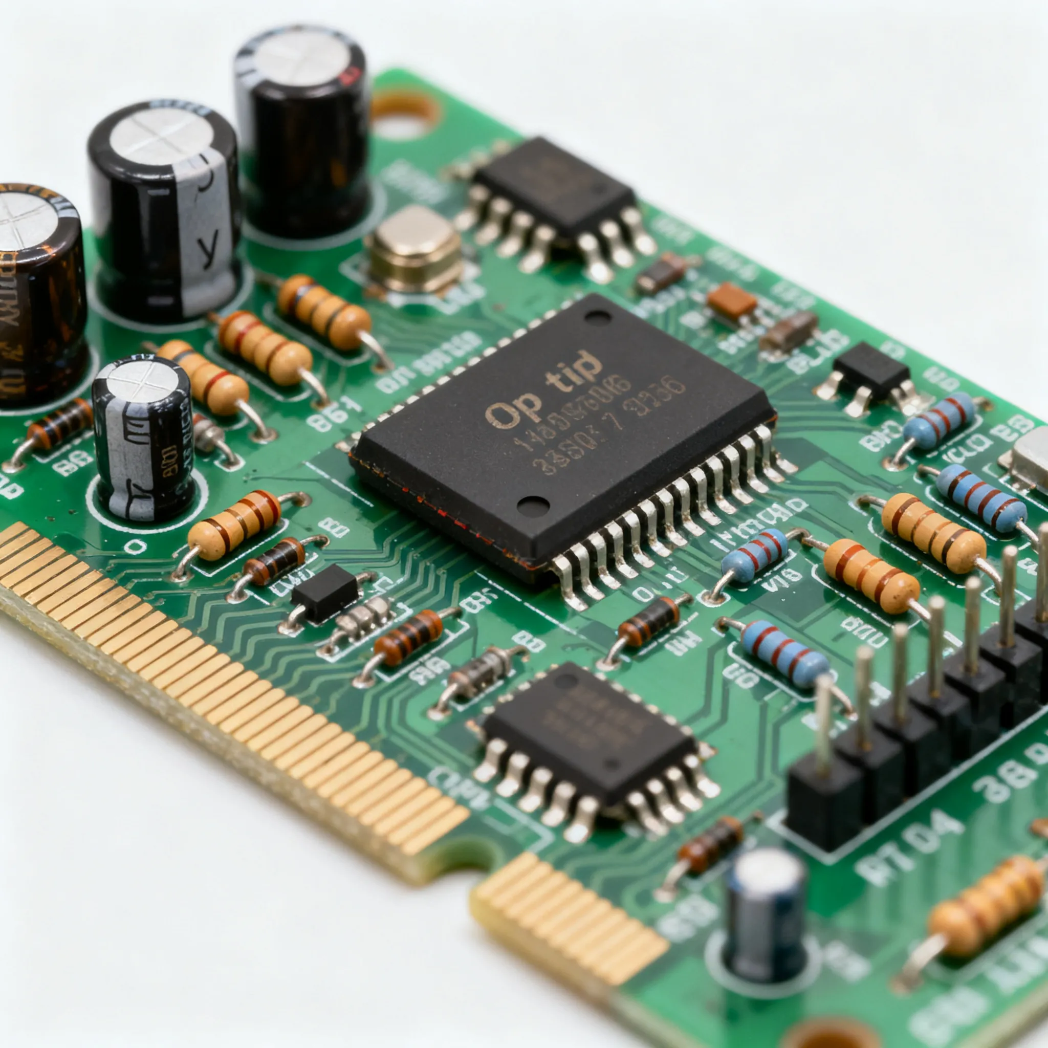
Stability is won or lost on the PCB. Even the most carefully compensated op-amp can break into song if the board speaks the wrong language. The following table maps the five most common pitfalls to corrective actions, each with a clear procurement note so that buyers and engineers can align on BOM choices early.
| Pitfall | Consequence | Corrective Action | Procurement Note |
|---|---|---|---|
| AC-coupling capacitor without DC bias resistor to ground | Input common-mode voltage drifts; output saturates or oscillates | Add a 100 kΩ–1 MΩ resistor from the non-inverting input to ground after the capacitor | Resistor value affects input impedance; include in BOM early and verify with datasheet bias current specs |
| Driving a capacitive load directly (e.g., ADC reference pin bypassed with 100 nF) | Output resistance and load capacitance form a pole inside the loop, eroding phase margin | Insert a 10–50 Ω series resistor between the op-amp output and the capacitive load; evaluate using RISO technique | Some op-amps have specified capacitive load drive; select parts with guaranteed stability for up to 100 pF without external compensation |
| Missing or poorly placed bypass capacitors | Supply impedance peaks at high frequencies, injecting phase shifts into the feedback loop | Place a 100 nF X7R ceramic capacitor within 2 mm of each supply pin, with a 10 µF bulk capacitor nearby | Specify capacitor dielectric and size; BV Circuits shows that bypassing the reference pin of an ADC driver is critical when the op-amp sees the capacitor as a load |
| Leaving unused op-amp channels floating in a dual or quad package | Floating inputs pick up noise, causing the unused amplifier to oscillate or draw excess current | Configure the unused channel as a voltage follower: connect output to inverting input, tie non-inverting input to a mid-supply reference or ground | Quad packages are cost-effective, but floating pins can cause field failures; ensure the BOM includes the necessary bias resistors |
| Misusing the offset-adjustment pins | Long traces to the trim pot act as antennas, and the pins can become unintended inputs, as PCBWay describes | Avoid using offset-null pins unless absolutely necessary; if used, keep traces short and shield them from noise | Many modern op-amps eliminate trim pins; choose a precision op-amp with low VOS to avoid the need for external nulling |
Layout discipline extends beyond the op-amp itself. iChome emphasizes that poor grounding, capacitive coupling from digital traces, and long feedback loops all degrade stability. From a procurement perspective, insisting on op-amps that explicitly provide phase margin curves and capacitive load drive data in the datasheet is a smart filter. It reduces the risk of locking in a part that requires heroic layout efforts to stay quiet. When qualifying a second source, request the same stability metrics and compare them under identical load conditions. A pin-compatible alternative that shows 5° less phase margin could be the difference between a clean release and a late-stage oscillation nightmare.
Key BOM stabilization checklist:
- Include a 100 nF bypass capacitor for every supply pin, placed as close to the package as possible.
- Specify the DC bias resistor to ground for any AC-coupled input path, and verify the op-amp’s bias current spec.
- Choose an op-amp with a documented capacitive load drive rating; if unavoidable, add an isolation resistor and simulate the loop gain.
- For quad packages, add the termination resistors for unused channels in the schematic and BOM from the start.
- Always request stability data—phase margin and gain margin—from the manufacturer or distributor, and cross-check with your own evaluation.
What Senior Engineers and Buyers Ask About Op-Amp Oscillation Risks
Q: How can I quickly tell if my op-amp circuit is oscillating?
Look for unexpected high-frequency signals on the output with an oscilloscope, often superimposed on the desired waveform. Check for overheating, erratic behavior, or excessive noise. A simple test is to touch the feedback path—if the frequency changes, you likely have parasitic oscillation. Use a spectrum analyzer if the frequency is beyond your scope’s bandwidth. The Engineering Knowledge provides further troubleshooting steps, including measuring supply current and checking for DC offset drift.
Q: What is the single most common layout mistake that causes op-amp oscillation?
Poor power-supply decoupling and long feedback traces. Omitting a 100 nF bypass capacitor close to the supply pins, or routing the feedback path near noisy digital lines, introduces phase shifts that erode phase margin. Even a small capacitive load can cause a pole in the loop gain if the op-amp’s output resistance isn’t accounted for. Always keep the feedback loop as short as possible and shield it from fast-switching signals.
Q: When should I pay extra for a unity-gain stable op-amp versus a decompensated type?
If your circuit operates at low closed-loop gain (e.g., a buffer or G=2), unity-gain stability is mandatory. Sacrificing it can lead to sustained oscillation. Decompensated parts are viable only if you guarantee a minimum gain, and they can offer higher bandwidth for a given power budget. Always verify the minimum stable gain spec and consider the cost of re-spinning a board if the system gain drops below that threshold. The price difference can be substantial—high-speed decompensated parts often exceed $7—so involve procurement early to evaluate availability and second-source options.
Q: Can oscillation be caused by the op-amp itself, or is it always a design issue?
Both. Some op-amps are marginally stable under certain loads, but most oscillation stems from application conditions: driving capacitive loads, missing DC bias paths, or inadequate phase margin in the feedback network. Always check the datasheet for capacitive load drive capability and phase margin curves. If the part is stable in isolation but oscillates on your board, review layout and parasitic elements. A marginal op-amp may pass a bench test yet fail in volume production, so insist on robust stability margins.
Q: What are the risks of leaving unused op-amp channels in a quad package improperly terminated?
Floating inputs can pick up noise and cause the unused amplifier to oscillate or draw excessive current, potentially coupling interference into the active channels. The safe practice is to configure the unused op-amp as a voltage follower with the non-inverting input tied to a mid-supply reference or ground, avoiding floating nodes. Procure the necessary bias resistors and include them in the BOM for every assembly.
Q: How does oscillation affect procurement and supply chain decisions?
An oscillating design may force a last-minute part change, leading to shortages or single-sourcing risks. Engineers may lock in a specific high-speed op-amp that is stable in their layout, but buyers need second-source alternatives. Oscillation-related re-spins also extend lead times and increase costs. It’s wise to involve procurement early to identify multiple compliant op-amps with similar stability margins, and to stock safety buffer for any part that is the only known cure for a tricky layout.
References & Further Reading
- Common Electronics Design Pitfalls – Part 1: Top Op-Amp Mistakes to Avoid (BV Circuits)
- How to Troubleshoot OP-Amp Circuits (The Engineering Knowledge)
- Common failure modes for op-amps? (Reddit r/AskElectronics)
- Common Mistakes in Using Operational Amplifiers—and How to Avoid Them (iChome)
- If All Else Fails Read This Article: Avoid Common Problems When Designing Amplifier Circuits (Analog Devices)
- Error in op-amp circuit design (Electrical Engineering Stack Exchange)
- Op Amps for Everyone Design Guide (Rev. B) (MIT)
- 6 Misuses of Operational Amplifiers in the Design of Measurement and Control Circuits (PCBWay)
Stability is a discipline that spans design, layout, and procurement. When oscillation emerges late in a project, the cost is rarely just a few extra passives—it’s delayed shipments, disputed warranties, and the scramble to find a compatible alternative when the original part is out of stock. By building a BOM around op-amps with documented stability metrics, qualifying second sources before tape-out, and adhering to the layout rules above, you can avoid the most common traps. For mixed BOMs and flexible MOQ needs, visit IC-Online to find a wide range of operational amplifiers and supporting components with the supply chain transparency that both engineers and buyers demand.