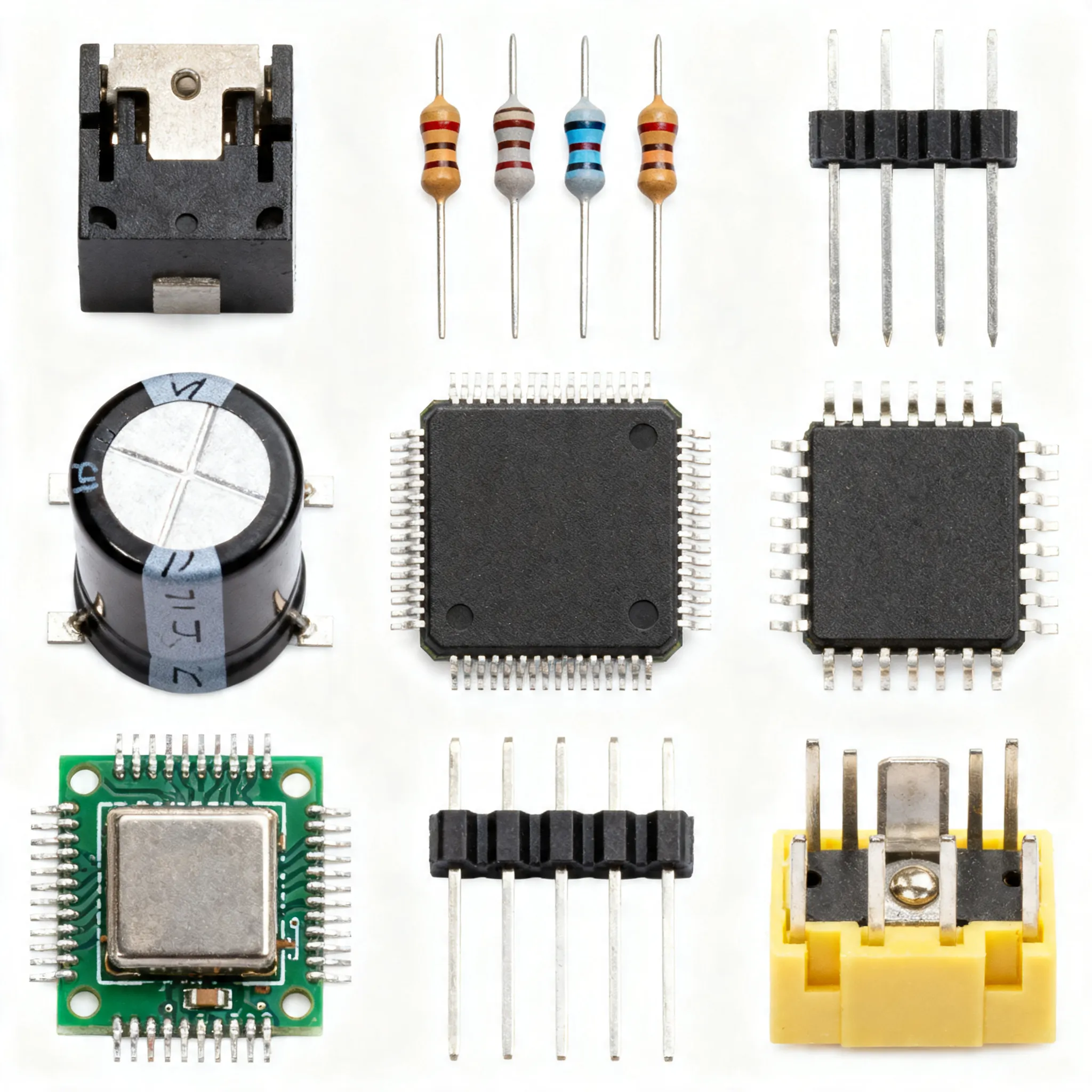
PCB Manufacturing: Key Processes and Quality Control Measures
PCB Manufacturing involves many precise steps that keep your electronic devices working safely and reliably. Each stage, from design to final testing, uses strict quality checks.
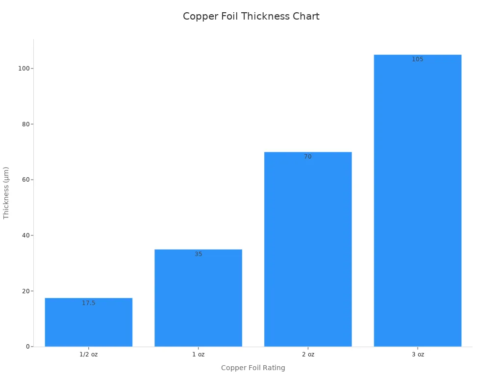
PCB Manufacturing involves many precise steps that keep your electronic devices working safely and reliably. Each stage, from design to final testing, uses strict quality checks. You can see how important accuracy is by looking at copper foil thickness and the number of layers in each board:
|
Parameter |
Numerical Values / Description |
|---|---|
|
Copper foil thickness |
1/2 oz (17.5 μm), 1 oz (35 μm), 2 oz (70 μm), 3 oz (105 μm) |
|
Number of PCB layers |
Single-sided, Double-sided, Multi-layer (3 or more conductive layers) |
Quality control methods, like AOI and X-ray inspection, help you avoid defects and keep performance high. These checks build trust and give you confidence in every finished board.
Key Takeaways
-
Start PCB manufacturing with a clear design and accurate file preparation to avoid costly errors and delays.
-
Use strong quality control methods like Automated Optical Inspection (AOI) and X-ray to catch surface and internal defects early.
-
Choose testing methods like In-Circuit Testing (ICT) or flying probe based on your production volume and flexibility needs.
-
Follow industry standards such as IPC, ISO, RoHS, and UL to ensure safety, reliability, and environmental compliance.
-
Work with reliable manufacturing partners and continuously improve your process to reduce defects and deliver high-quality PCBs.
PCB Manufacturing Steps
Concept and Design
You start every PCB Manufacturing project with a clear idea of what your circuit needs to do. You create a schematic diagram that shows how each electronic part connects. Next, you design the layout, placing each component and drawing the copper traces that link them. Good design helps you avoid problems later, like signal loss or overheating. Careful planning at this stage ensures your board will work as expected.
File Preparation
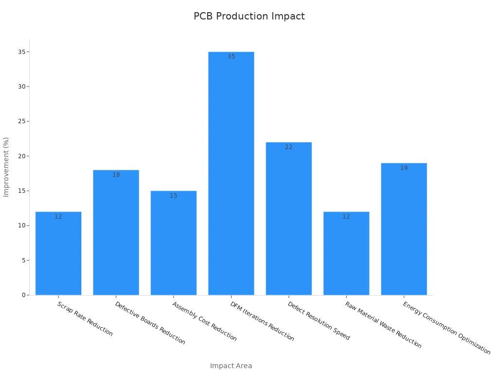
After you finish the design, you prepare files for production. These files include Gerber files, drill files, and a bill of materials. Accurate file preparation is critical. Even small mistakes can cause big problems, such as scrap or delays. Research shows that using advanced file preparation tools can reduce scrap rates by 12%, lower defective boards by up to 18%, and cut assembly costs by 15%. You can see the impact of file preparation accuracy in the table below:
|
Impact Area |
Outcome |
|---|---|
|
Scrap Rate Reduction |
12% reduction |
|
Defective Boards Reduction |
Up to 18% fewer defective boards |
|
Assembly Cost Reduction |
Up to 15% lower assembly costs |
|
DFM Iterations Reduction |
35% fewer design-for-manufacturability loops |
|
Defect Resolution Speed |
22% faster resolution |
|
Raw Material Waste Reduction |
12% less waste |
|
Energy Consumption Optimization |
19% less power used per square foot |
Boards with dimensional errors often get scrapped, which wastes materials and time. Careful file preparation helps you avoid these costly mistakes.
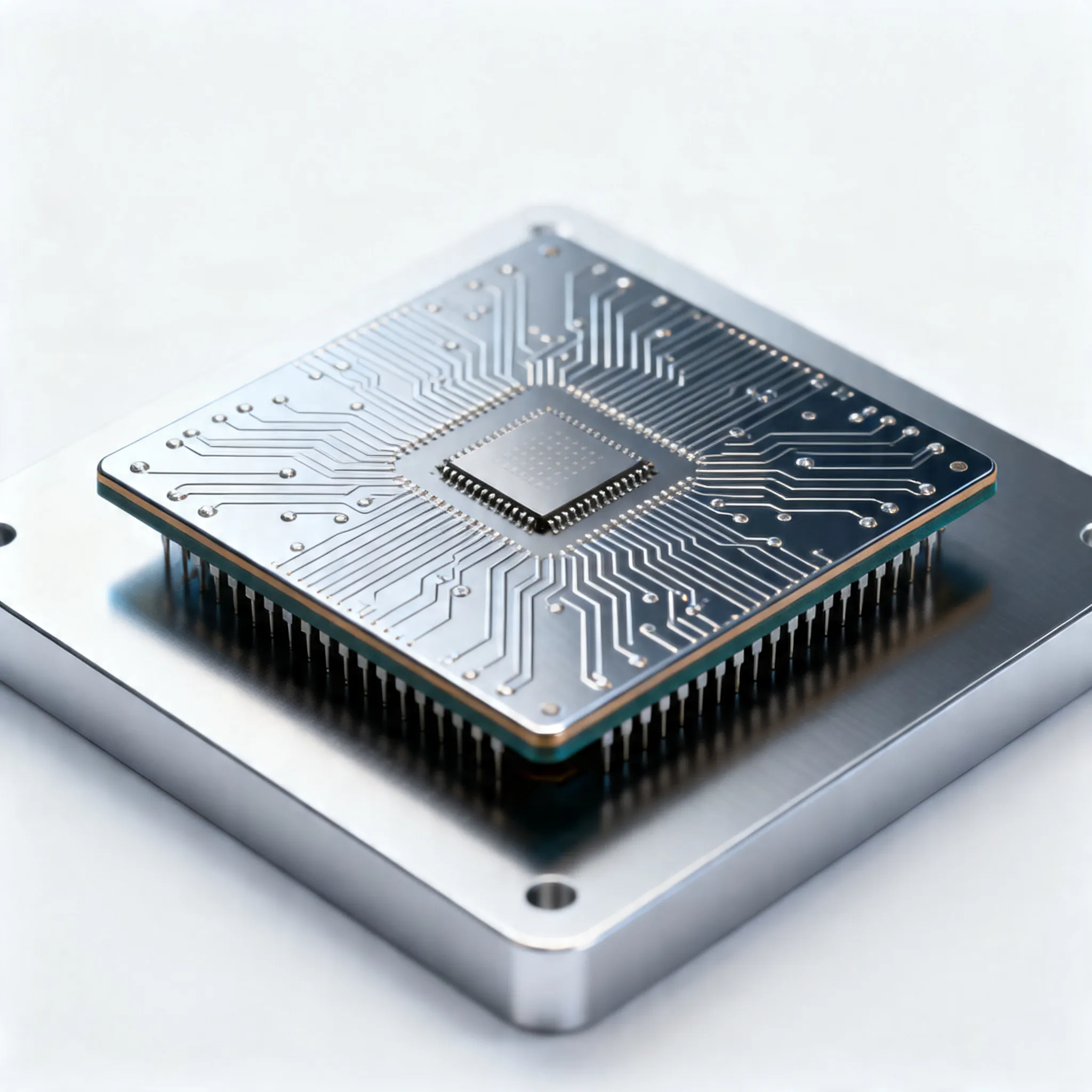
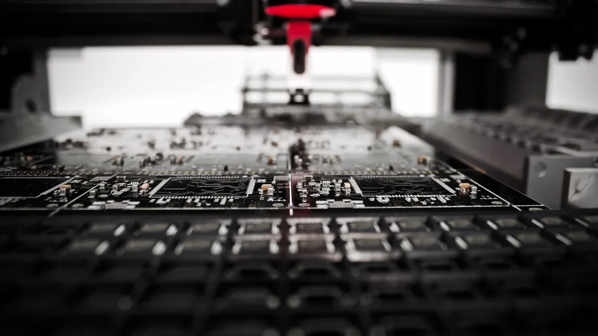
Fabrication
In the fabrication step, you turn your digital design into a real board. Machines print the copper traces, drill holes, and add layers. Quality control during fabrication is essential. One industry study showed that by controlling fabrication variations, manufacturers reduced their lot reject rate from 5500 to 900 parts per million. This means fewer faulty boards and better performance for your products.
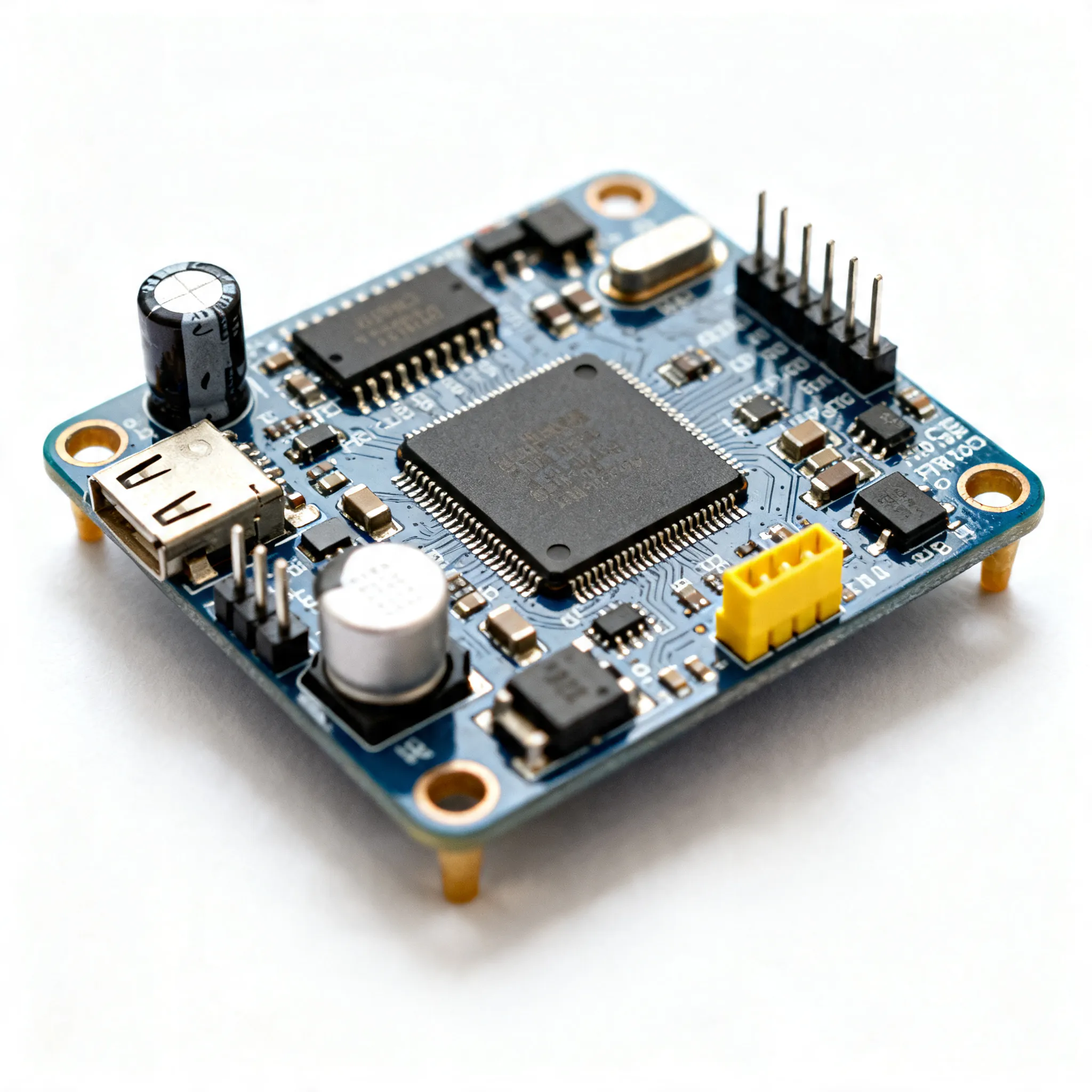
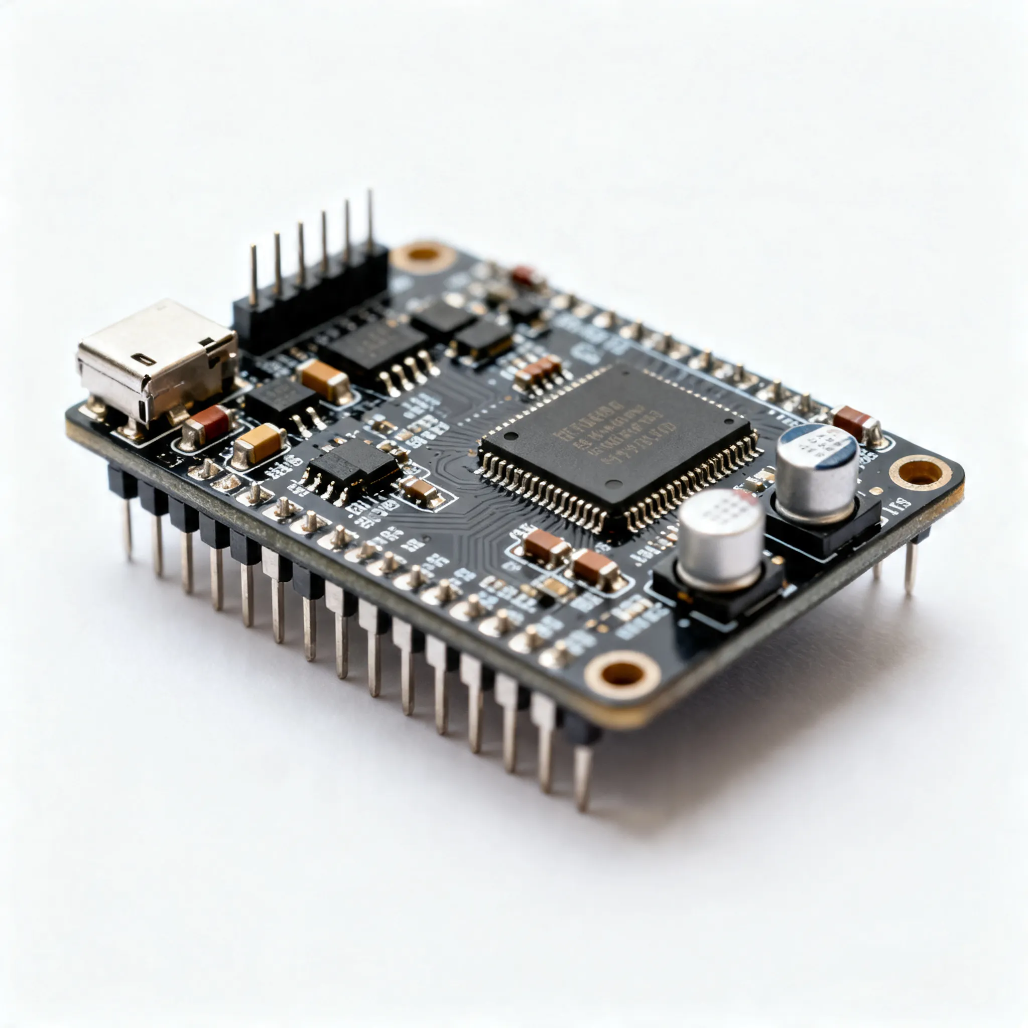
Assembly
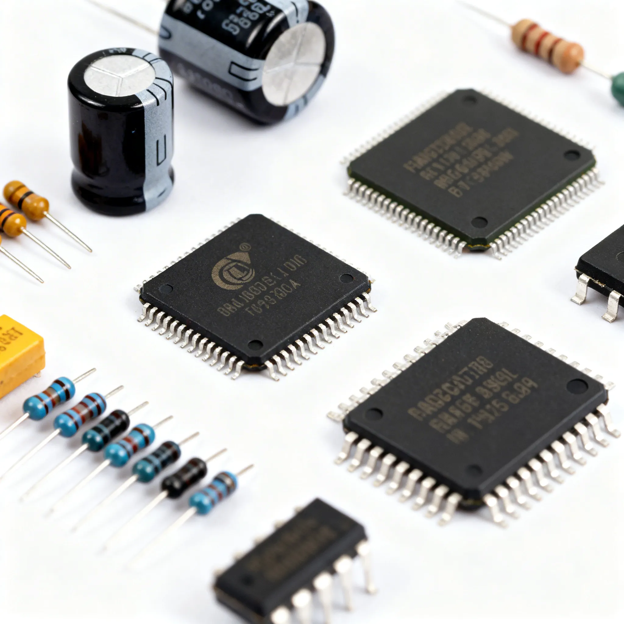
Assembly is where you place and solder components onto the board. This step is vital for reliable electronic connections. If you miss a defect here, it can cause open circuits, shorts, or even total failure. Careful inspection after assembly helps you catch problems before shipping. Surface mount and through-hole technologies both play a role, depending on your needs. High-quality assembly ensures your PCB Manufacturing process delivers boards that work every time.
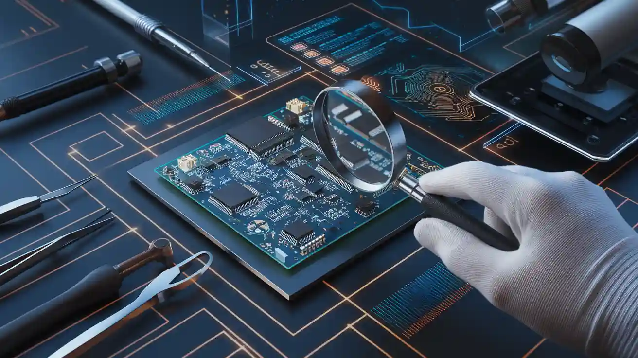
Quality Control
Quality control is the backbone of reliable PCB Manufacturing. You need to use several inspection and testing methods to catch defects early and ensure every board meets strict standards. Each method plays a unique role in finding problems and improving the final product.
Visual Inspection
You start with visual inspection to check for obvious surface defects. Skilled inspectors look for scratches, solder bridges, missing components, and misalignments. Manual visual inspection is simple and low-cost, but it depends on human attention and can miss small or hidden issues. Fatigue and oversight can lead to mistakes, especially in high-volume production.
|
Performance Metric |
Manual Visual Inspection (MVI) |
X-Ray Inspection |
|
|---|---|---|---|
|
Defect Detection Scope |
Surface defects only |
Surface defects only |
Internal defects only |
|
Inspection Speed |
Slower, limited by human factors |
Faster, automated and consistent |
Slower due to complex image processing |
|
Accuracy (Detection Rate) |
Prone to human error, variable |
Higher detection rate, especially for complex boards |
High accuracy for internal defects |
|
False Positives/Negatives |
Higher risk due to human fatigue and oversight |
Reduced but still present, depends on algorithm accuracy |
Lower false negatives for internal defects |
|
Training Requirements |
Skilled inspectors needed |
Less operator training after setup |
Specialized training required |
|
Equipment Cost |
Low |
High initial investment |
Very high cost and complexity |
|
Non-Destructive Testing |
No |
No |
Yes |
Manual inspection works best for simple boards or small batches. For complex or high-volume production, you need more advanced methods.
AOI and X-ray
Automated Optical Inspection (AOI) uses cameras and software to scan boards for surface defects. AOI systems work faster and more accurately than humans, especially on complex boards. They use image processing and pattern recognition to spot missing parts, soldering issues, and misalignments. AOI does not damage the board, making it a safe choice for routine checks. Recent advances in deep learning have made AOI even better at finding new or subtle defects, but these systems need large, well-labeled datasets to reach their full potential.
Automated X-ray Inspection (AXI) looks inside the board to find hidden problems. You can use X-ray to detect solder voids, shorts under BGAs, and internal cracks that AOI cannot see. AXI is essential for high-reliability sectors like aerospace and medical devices. It uses differences in material density to reveal defects, and it can reach a resolution of about 2 micrometers for fine-pitch components. X-ray inspection costs more and takes longer, but it gives you a complete picture of the board’s quality.
AOI and X-ray together give you strong coverage for both surface and internal defects, making your quality control much more thorough.
ICT and Flying Probe
In-Circuit Testing (ICT) and flying probe tests check the electrical performance of your boards. ICT uses custom fixtures to test each component and connection quickly. It works best for high-volume production, where the upfront cost of fixtures pays off over time. ICT can test complex parts like BGAs and FPGAs, and it finds faults fast, often in about one minute per board.
Flying probe testing uses moving probes to touch test points on the board. You do not need custom fixtures, so it is ideal for prototypes and small batches. Flying probe systems can access tiny pads and are easy to reprogram for new designs. They take longer per board but offer great flexibility and coverage, especially for complex or low-volume products.
|
Aspect |
ICT Advantages |
Flying Probe Advantages |
|---|---|---|
|
Test Cycle Time |
Very fast (~1 minute per board) |
Longer (up to 15 minutes per board) |
|
Cost per Unit (High Volume) |
Lower after fixture development |
Higher due to longer test time |
|
Upfront Cost |
High (custom tooling and fixture required) |
Low (no custom tooling needed) |
|
Flexibility |
Less flexible; suited for mature, high-volume products |
Highly flexible; ideal for prototypes and low-volume runs |
|
Test Coverage |
Tests individual components including BGAs and FPGAs; logic functionality |
Accesses smaller pads without dedicated test points; improved coverage for complex boards |
|
Test Types |
Detects shorts, opens, resistance, capacitance, component orientation; soldering integrity checks |
Detects shorts, opens, resistance, capacitance, component orientation; LED testing capability |
|
Programming & Setup |
Requires programming and custom tooling; longer lead time |
Easier programming using CAD data; shorter setup time |
|
Suitability |
Best for mature, high-volume production |
Best for early-stage development and low-volume production |
ICT and flying probe tests help you catch electrical faults before your boards leave the factory, saving time and money.
Functional and Burn-in
Functional testing checks if your board works as intended in real-world conditions. You apply power and run test programs to make sure every function operates correctly. This step is vital for products in consumer electronics, healthcare, and other fields where safety and performance matter.
Burn-in testing pushes your boards to their limits. You expose them to high temperatures and voltages to find early-life failures. This process simulates years of use in just a few hours or days. Burn-in testing is especially important for boards used in harsh environments, like aerospace or industrial machines. It helps you find hidden defects and ensures your boards will last for many years.
Functional and burn-in tests are key for long-term reliability. They help you deliver products that work safely and consistently, even in tough conditions.
Process Controls
Process controls keep your manufacturing consistent and efficient. You monitor every step, from solder paste application to final inspection. Automated systems track placement accuracy, solder volume, and temperature profiles. You use statistical process control (SPC) to spot trends and fix problems before they cause defects.
|
Industry Sector |
Process Control Impact |
Key Metrics / Outcomes |
|---|---|---|
|
Consumer Electronics |
Fully automated assembly line |
- Production capacity ↑ from 10,000 to 85,000 units/day |
|
- Defect rate ↓ from 2% to 0.02% |
||
|
- Time-to-market ↓ by 65% |
||
|
- Labor cost ↓ by 78% per unit |
||
|
- Energy consumption ↓ by 42% per unit |
||
|
Automotive Electronics |
Transition from semi-automated to fully automated |
- First-pass yield ↑ from 92% to 99.7% |
|
- Warranty claims ↓ by 83% |
||
|
- Production flexibility for 230+ variants |
||
|
- Manufacturing space utilization ↑ by 45% |
||
|
- Achieved ISO/TS 16949 compliance |
||
|
Medical Device Startup |
Selective automation with traceability |
- FDA compliance achieved |
|
- Validation time ↓ by 70% |
||
|
- Zero-defect manufacturing maintained |
||
|
- Production scaled from 100 to 5,000 units/month |
||
|
- Time-to-market ↓ from 18 to 7 months |
You also document every process and result. This documentation helps you trace problems, improve yields, and meet industry standards. By using process controls, you can reduce defects, boost production, and deliver high-quality boards every time.
About 20% of electronic failures come from manufacturing defects. Strong quality control and process monitoring help you avoid costly recalls and keep your customers happy.
Industry Standards
IPC
You will find IPC standards at the heart of PCB manufacturing. IPC creates over 300 active standards that guide you in making reliable and consistent boards. These standards cover everything from design to assembly. Many professionals around the world use IPC rules to make sure their products meet customer expectations. The annual IPC report on the North American PCB Industry gives you important market data and trends. This report helps you see how IPC standards support business growth and quality. IPC also runs a program that collects sales and order data from PCB makers. This data lets you compare your performance with others and track market changes. When you follow IPC standards, you build trust with your customers and improve your products.
ISO
ISO standards help you set up strong quality management systems. You use ISO 9001 to make sure your processes are clear and repeatable. ISO 14001 helps you protect the environment during production. Many companies also use OHSAS 18001 to keep workers safe. Studies show that when you follow these standards, you reduce defects and improve safety. You can use tools like Design for Manufacturability (DFM) analysis and Automated Optical Inspection (AOI) to catch problems early. Companies that use ISO systems often see fewer mistakes and better products. You also show your customers that you care about quality and safety.
RoHS
RoHS standards protect people and the planet from harmful chemicals. You must avoid using substances like lead, mercury, and certain flame retardants in your boards. Over 130 countries now require RoHS compliance. When you follow RoHS, you help reduce toxic waste and make your products safer for everyone. Before RoHS, tin whiskers caused a 5% failure rate in Swiss Swatch watches, leading to costly recalls. Now, RoHS-compliant boards have better thermal shock resistance and improved soldering. You also lower health risks for workers and avoid legal trouble. RoHS makes your boards safer and more marketable.
UL
UL certification shows that your PCBs meet strict safety standards. You use UL tests to check for fire resistance and electrical safety. Many customers look for the UL mark before they buy. When you get UL approval, you prove that your boards can handle tough conditions without failing. This certification helps you enter new markets and gives your customers peace of mind. You also reduce the risk of recalls and product failures. UL standards help you build safer, more reliable electronics.
Best Practices
Design for Manufacturability
You can make PCB Manufacturing smoother by following Design for Manufacturability (DFM) principles. DFM helps you avoid problems during production. If you set very tight design rules, like small copper spacing everywhere, you may see more defects. Wider spacing where possible lowers the risk of shorts from etching or solder mask errors. Real-world production can shift small features, so your design rules should allow for these changes. You should talk with your manufacturer early, especially if you want to use non-standard features. This teamwork leads to better results and fewer delays.
Tip: Use IPC standards like IPC-2221 and IPC-4761. These help you set good design rules and improve reliability.
A good DFM approach includes:
-
Planning trace width and spacing for easier production.
-
Managing annular rings to avoid drill breakouts.
-
Optimizing via design.
-
Applying solder mask and silkscreen correctly.
Reliable Partners
Choosing the right manufacturing partner makes a big difference. Reliable partners follow strict quality standards, such as IPC-6012 and ISO 9001. They deliver high-quality boards with fewer defects. Local manufacturers can offer faster turnaround and better communication. You get quicker problem-solving and support for your project. Strong partnerships also protect your intellectual property and help your local economy.
Here are some things to look for in a partner:
-
Quality certifications and strong quality control.
-
Experience with your industry and design needs.
-
Advanced equipment and enough capacity.
-
Consistent lead times and delivery.
-
Clear pricing and good customer support.
Continuous Improvement
You should always look for ways to improve your process. Use automated inspection, electrical tests, and stress tests to find and fix problems early. Following IPC standards helps you keep quality high. Many companies use "Right First Time" methods to reduce defects and save money. For example, using process mapping and operator training can raise your yield and lower costs. Regular reviews and data analysis help you spot trends and make smart changes.
Note: Companies that use continuous improvement often see fewer defects, higher productivity, and happier customers.
Manufacturer Evaluation
When you pick a PCB manufacturer, you need to check several factors. The table below shows what to consider:
|
Why It Matters |
|
|---|---|
|
Technology and Equipment |
Needed for complex designs |
|
Material Options |
Affects board performance and cost |
|
Surface Finish Choices |
Impacts soldering and reliability |
|
Layer Count Capabilities |
Important for multi-layer boards |
|
Minimum Trace Width & Spacing |
Sets design limits |
|
Minimum Drill Hole Size |
Influences component choice |
|
Impedance Control |
Needed for high-speed signals |
|
Quality Control & Certifications |
Ensures reliability and compliance |
|
Cost Analysis |
Helps balance price and quality |
|
Turnaround Time Factors |
Affects project deadlines |
|
Customer Support & Reviews |
Shows reliability and service quality |
You should also check customer feedback and how quickly the manufacturer responds to questions. Good communication and technical support make your project run smoothly.
You can achieve reliable results in PCB Manufacturing by following precise steps and strong quality control.
-
You ensure safety, reliability, and high performance by meeting industry standards.
-
Early defect detection lowers costs and boosts customer satisfaction.
-
Data from testing helps you improve your process and reduce risks.
Comparative reports show that IPC standards give you better product consistency and reliability. Use the evaluation criteria to choose the right manufacturer. Review your current process or consult with experts to keep improving.
FAQ
What is the most important quality control step in PCB manufacturing?
You should focus on Automated Optical Inspection (AOI). AOI finds surface defects quickly and accurately. It helps you catch problems early. This step improves your board’s reliability and reduces costly rework.
How do you choose the right PCB manufacturer?
You need to check certifications, equipment, and customer reviews. Look for ISO 9001 and IPC standards. Reliable support and clear communication matter. Use a checklist to compare options.
Tip: Ask for sample boards before placing a large order.
Why do you need RoHS compliance?
RoHS keeps your boards free from harmful chemicals like lead and mercury. You protect users and the environment. Many countries require RoHS for electronics. You also avoid legal issues and improve your product’s marketability.
Can you use the same PCB design for different products?
You can reuse a PCB design if the products have similar requirements. Check voltage, current, and component needs. Sometimes, you must adjust the layout or materials. Always test the board in each new product.
What happens if you skip burn-in testing?
You risk early failures in your products. Burn-in testing finds weak components by stressing the board. Skipping this step can lead to more returns and unhappy customers.