RF vs Microwave Components: Key Differences and Application Considerations
Understanding the differences between RF vs Microwave Components is crucial for engineers who design electronic systems that need to perform reliably and have long lifespans.

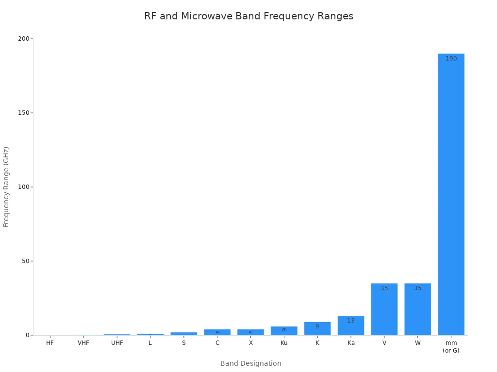
Understanding the differences between RF vs Microwave Components is crucial for engineers who design electronic systems that need to perform reliably and have long lifespans. According to international standards, radio frequency components operate from 50 MHz to 1 GHz, while microwave components cover the range from 1 GHz to 30 GHz. This classification aligns with what most engineers use in their projects. The table below outlines the IEEE radar band names, which clarify the starting and ending points of each frequency range:
|
Band Designation |
Frequency Range (GHz) |
Description/Notes |
|---|---|---|
|
HF |
0.003 to 0.03 |
High Frequency |
|
VHF |
0.03 to 0.3 |
Very High Frequency |
|
UHF |
0.3 to 1 |
Ultra High Frequency |
|
L |
1 to 2 |
Long Wave (Microwave start) |
|
S |
2 to 4 |
Short Wave |
|
C |
4 to 8 |
Between S and X bands |
|
X |
8 to 12 |
Used in radar/fire control |
|
Ku |
12 to 18 |
Kurz-under |
|
K |
18 to 27 |
Kurz (short) |
|
Ka |
27 to 40 |
Kurz-above |
|
V |
40 to 75 |
- |
|
W |
75 to 110 |
Alphabetical follow-up |
|
mm (or G) |
110 to 300 |
Millimeter wave band |
These technical distinctions between RF vs Microwave Components influence how signals propagate and how components interact within a system. Ultimately, understanding these differences helps engineers select the most suitable components for each specific application.
Key Takeaways
-
RF components use lower frequencies and can go through things better. This makes them good for long-distance communication like cell phones and radios. Microwave components use higher frequencies and have shorter wavelengths. They need special materials and careful designs to stop signal loss and heat problems. Making microwave circuits needs careful control of signal paths and materials. This helps lower noise and interference, which is harder than with RF designs. Picking the right component depends on the frequency, power, place, and data needs of the job. This helps make sure the system works well and is reliable. Using trusted suppliers and the right PCB materials helps engineers build strong RF and microwave systems that last a long time.
Radio Frequency and Microwave Basics

What is Radio Frequency?
Radio frequency is a part of the electromagnetic spectrum. These waves move between 3 kHz and 300 GHz. In electronics, rf waves travel at the speed of light. Rf waves move back and forth very quickly. This helps send and receive signals. Engineers use rf currents to make electric fields that change direction. These fields can heat things or send information. The rf spectrum has many different frequencies. Lower frequencies have longer wavelengths. Higher frequencies have shorter wavelengths. Rf signals can go through buildings and travel far. They are used in AM/FM radio, TV, and wireless devices. Rf energy can move through many places. This makes it important for today’s technology.
-
Radio frequency waves:
-
Go from 3 kHz to 300 GHz in the spectrum.
-
Have wavelengths from 100 kilometers to 1 millimeter.
-
Allow many types of signals for communication.
-
What is Microwave?
Microwave is a smaller part of the rf spectrum. It usually covers 1 GHz to 300 GHz. Microwaves have shorter wavelengths, from 1 millimeter to 1 meter. These frequencies need special parts because microwaves act differently than lower rf. Microwave signals mostly move in straight lines. They do not bend around things easily. Devices like klystron tubes, magnetrons, and solid-state diodes make microwave energy. Microwave signals can lose strength and get absorbed, especially at high frequencies. This limits how far they can go. Engineers use microwaves in radar, satellites, and wireless networks.
|
Characteristic |
Microwave Range |
Radio Wave Range |
|---|---|---|
|
Wavelength |
1 millimeter to 1 meter |
1 meter or more |
|
Frequency |
300 GHz to 300 MHz |
300 MHz or less |
|
Photon Energy |
1.24 meV to 1.24 μeV |
1.24 μeV or less |
Microwave signals can heat things below the surface. This is used in microwave ovens and some medical tools.
Frequency Range Overview
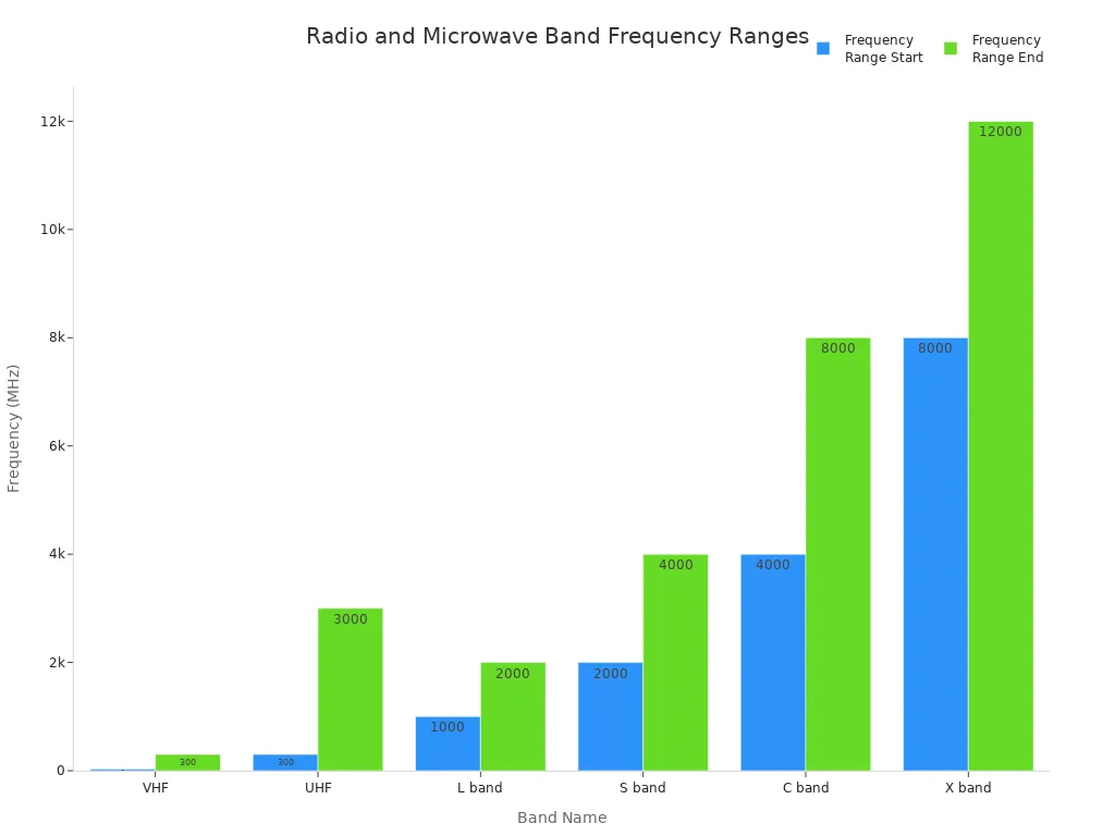
The electromagnetic spectrum has both rf and microwave bands. Groups like IEEE and ITU set the standard ranges for each band. The rf spectrum starts at 3 kHz and goes up to 300 GHz. Microwaves are at the higher end. The table below lists common bands and what they are used for:
|
Band Name |
Frequency Range |
Typical Applications |
|---|---|---|
|
VHF |
30 to 300 MHz |
FM radio, TV |
|
UHF |
300 MHz to 3 GHz |
TV, cell phones, wireless LAN, Bluetooth |
|
L band |
1 to 2 GHz |
GPS, military, radar |
|
S band |
2 to 4 GHz |
Microwave ovens, weather radar, communications |
|
C band |
4 to 8 GHz |
Long-distance calls |
|
X band |
8 to 12 GHz |
Radar, satellites |
Rf and microwave signals move in different ways. Lower rf frequencies can go past the horizon and through things. Microwave signals need a clear path and are more affected by the environment. Higher frequencies have more bandwidth. This means microwave systems can send more data. Engineers must think about these differences when building systems for certain uses.
RF vs Microwave Components
Design Differences
Engineers use different ways to design rf vs microwave components. As frequency goes up, the size of each assembly changes. In rf and microwave pcb assembly, the signal’s wavelength matters a lot. At lower frequencies, traces and parts are much smaller than the wavelength. This makes layouts simple and transmission line effects less important. When the frequency gets into the microwave range, the assembly and traces get close in size to the wavelength. Now, transmission line effects become very important.
-
Engineers pick pcb materials with smooth surfaces and the right copper thickness. These choices help stop signal loss at high frequency.
-
Thinner pcb cores keep signals strong and help control heat. Cores that move heat well make temperature steady and help parts last longer.
-
Multi-layer pcb stack-ups keep rf and non-rf parts apart. Special ground and power planes cut down on noise and interference.
-
Designers put rf and microwave components on the top layer. Ground planes go right under them to give good grounding and stop electromagnetic interference.
-
In microwave assembly, the circuit uses both lumped and distributed elements. Transmission lines, breaks, and matching impedance are very important.
Microwave components often use ferrites and ferroelectrics to tune devices. These materials help make isolators and phase shifters without extra power. The assembly’s length must match the wavelength for it to work right. This is not needed for lower-frequency rf assembly, where these effects do not matter as much.
Performance Factors
How well rf vs microwave components work depends on many things. Signal loss gets worse as frequency goes up. In rf and microwave pcb assembly, longer traces lose more signal, especially when they get close to the wavelength. Impedance mismatches cause return loss, which is worse at higher frequency. Microwave signals are more sensitive to noise and reflections.
-
Crosstalk gets worse with higher frequency and more pcb parts. Designers must keep signals apart, not run traces side by side, and use the right ends.
-
Dielectric losses in pcb materials go up with frequency. FR-4 materials lose more energy, so insertion loss is higher at microwave frequencies.
-
Special laminates like Teflon lower dielectric loss and help at high frequency.
-
Skin effect losses also go up with frequency, making signals weaker.
-
Good pcb design, with impedance control and solid ground planes, is needed for reliable assembly.
Temperature stability and reliability are different too. Microwave components often face bigger temperature changes because of more power. Materials that handle heat well help keep performance steady and make assemblies last longer.
Comparison Table
The table below shows the main differences between rf vs microwave components. It lists frequency range, design, power handling, efficiency, materials, assembly, and cost.
|
Feature |
RF Components |
Microwave Components |
|---|---|---|
|
Frequency Range |
50 MHz – 1 GHz |
1 GHz – 30 GHz |
|
Spectrum Position |
Lower part of radio frequency spectrum |
Higher part of radio frequency spectrum |
|
Design Approach |
Lumped elements, simple layouts |
Distributed elements, transmission lines |
|
PCB Materials |
Standard FR-4, moderate cost |
Teflon, ceramic-filled PTFE, higher cost |
|
PCB Assembly |
Thicker cores, fewer layers |
Thinner cores, multi-layer stack-ups |
|
Signal Loss |
Lower, less sensitive to layout |
Higher, requires precise layout |
|
Power Handling |
Higher, less heat buildup |
Lower, more heat, needs thermal management |
|
Efficiency |
Moderate to high |
Lower due to higher losses |
|
Size Considerations |
Not wavelength-dependent |
Physical size matches wavelength |
|
Noise Sensitivity |
Lower |
Higher |
|
Reliability |
High, less affected by temperature |
Needs careful temperature management |
|
Cost and Availability |
Lower cost, widely available |
Higher cost, specialized materials |
Note: Microwave components are a type of rf component. They need special design because of higher frequency, more signal loss, and stricter assembly rules. Engineers must think about modulation, bandwidth, and stopping interference when working with microwaves.
New rf and microwave pcb assembly parts can work above 130 GHz. Gallium nitride amplifiers and fast converters are better now. Open standards like SOSA and OpenRFM help make assemblies that are modular, reliable, and flexible for defense and business. The materials used, like ceramic-filled PTFE, change both cost and performance. High-end materials work better but make assembly harder and more expensive.
Industry standards from Mercury Systems and OSHA help keep rf and microwave components safe and effective. These rules cover how to use, build, and keep assemblies working well and safely.
Applications and Use Cases
RF Applications
RF components are important in many devices today. They send signals far and can go through walls. This makes them great for communication and broadcasting. Engineers use RF in things like mobile phones, Wi-Fi, and Bluetooth. These systems use RF to send voices, data, and videos. Remote controls, smart home gadgets, and wireless speakers also use RF. This makes them easy and fun to use. Cell towers and base stations use RF for strong data signals. Satellites use RF for TV, GPS, and military talks. RF uses AM and FM to send radio signals. Wi-Fi uses higher RF bands for short-range connections.
-
Some RF uses are:
-
Mobile phones and wireless networks
-
Radio and TV broadcasting
-
Smart home gadgets and remotes
-
GPS and satellite communication
-
Microwave Applications
Microwave parts are used when high frequency is needed. They help in radar, satellites, and special medical tests. Radar uses microwaves to see objects and track movement. Medical tests use microwaves to find cancer early. Factories use microwaves to check if things are safe and strong. Airports use microwaves in body scanners to find hidden items. Energy companies test wind turbines and pipes with microwaves to check for damage.
|
Application Area |
|
|---|---|
|
Medical Imaging |
Finding cancer early, mapping tissues |
|
Radar Systems |
Focusing images, finding objects |
|
Non-Destructive Testing (NDT) |
Checking airplane, car, and building materials |
|
Structural Health Monitoring |
Finding rust or problems in concrete |
|
Security |
Airport body scanners |
|
Energy Supply |
Testing wind turbines and pipes |
Choosing the Right Component
Picking RF or microwave parts depends on what you need. Lower RF signals go farther and through things. They are good for long-distance and country areas. Microwave signals carry more data but do not go as far. They are good for fast satellite links and radar. Engineers must think about where the part will be used, how fast it must send data, and how far it must reach. For important jobs, the part must be safe and work well. In communication, designers use special pcb materials like RO3006 or RT/Duroid for best results. Radar and medical jobs need strong capacitors and careful assembly. Factories use EMI filters and non-magnetic parts for strong machines. The right pcb and assembly help keep things working safely and by the rules.
Tip: Always pick parts and pcb materials that fit your job for the best results.
Key Takeaways
-
RF components use lower frequencies and can go through things better. This makes them good for long-distance communication like cell phones and radios. Microwave components use higher frequencies and have shorter wavelengths. They need special materials and careful designs to stop signal loss and heat problems. Making microwave circuits needs careful control of signal paths and materials. This helps lower noise and interference, which is harder than with RF designs. Picking the right component depends on the frequency, power, place, and data needs of the job. This helps make sure the system works well and is reliable. Using trusted suppliers and the right PCB materials helps engineers build strong RF and microwave systems that last a long time.
Radio Frequency and Microwave Basics
What is Radio Frequency?
Radio frequency is a part of the electromagnetic spectrum. These waves move between 3 kHz and 300 GHz. In electronics, rf waves travel at the speed of light. Rf waves move back and forth very quickly. This helps send and receive signals. Engineers use rf currents to make electric fields that change direction. These fields can heat things or send information. The rf spectrum has many different frequencies. Lower frequencies have longer wavelengths. Higher frequencies have shorter wavelengths. Rf signals can go through buildings and travel far. They are used in AM/FM radio, TV, and wireless devices. Rf energy can move through many places. This makes it important for today’s technology.
-
Radio frequency waves:
-
Go from 3 kHz to 300 GHz in the spectrum.
-
Have wavelengths from 100 kilometers to 1 millimeter.
-
Allow many types of signals for communication.
-
What is Microwave?
Microwave is a smaller part of the rf spectrum. It usually covers 1 GHz to 300 GHz. Microwaves have shorter wavelengths, from 1 millimeter to 1 meter. These frequencies need special parts because microwaves act differently than lower rf. Microwave signals mostly move in straight lines. They do not bend around things easily. Devices like klystron tubes, magnetrons, and solid-state diodes make microwave energy. Microwave signals can lose strength and get absorbed, especially at high frequencies. This limits how far they can go. Engineers use microwaves in radar, satellites, and wireless networks.
|
Characteristic |
Microwave Range |
Radio Wave Range |
|---|---|---|
|
Wavelength |
1 millimeter to 1 meter |
1 meter or more |
|
Frequency |
300 GHz to 300 MHz |
300 MHz or less |
|
Photon Energy |
1.24 meV to 1.24 μeV |
1.24 μeV or less |
Microwave signals can heat things below the surface. This is used in microwave ovens and some medical tools.
Frequency Range Overview
The electromagnetic spectrum has both rf and microwave bands. Groups like IEEE and ITU set the standard ranges for each band. The rf spectrum starts at 3 kHz and goes up to 300 GHz. Microwaves are at the higher end. The table below lists common bands and what they are used for:
|
Band Name |
Frequency Range |
Typical Applications |
|---|---|---|
|
VHF |
30 to 300 MHz |
FM radio, TV |
|
UHF |
300 MHz to 3 GHz |
TV, cell phones, wireless LAN, Bluetooth |
|
L band |
1 to 2 GHz |
GPS, military, radar |
|
S band |
2 to 4 GHz |
Microwave ovens, weather radar, communications |
|
C band |
4 to 8 GHz |
Long-distance calls |
|
X band |
8 to 12 GHz |
Radar, satellites |
Rf and microwave signals move in different ways. Lower rf frequencies can go past the horizon and through things. Microwave signals need a clear path and are more affected by the environment. Higher frequencies have more bandwidth. This means microwave systems can send more data. Engineers must think about these differences when building systems for certain uses.
RF vs Microwave Components
Design Differences
Engineers use different ways to design rf vs microwave components. As frequency goes up, the size of each assembly changes. In rf and microwave pcb assembly, the signal’s wavelength matters a lot. At lower frequencies, traces and parts are much smaller than the wavelength. This makes layouts simple and transmission line effects less important. When the frequency gets into the microwave range, the assembly and traces get close in size to the wavelength. Now, transmission line effects become very important.
-
Engineers pick pcb materials with smooth surfaces and the right copper thickness. These choices help stop signal loss at high frequency.
-
Thinner pcb cores keep signals strong and help control heat. Cores that move heat well make temperature steady and help parts last longer.
-
Multi-layer pcb stack-ups keep rf and non-rf parts apart. Special ground and power planes cut down on noise and interference.
-
Designers put rf and microwave components on the top layer. Ground planes go right under them to give good grounding and stop electromagnetic interference.
-
In microwave assembly, the circuit uses both lumped and distributed elements. Transmission lines, breaks, and matching impedance are very important.
Microwave components often use ferrites and ferroelectrics to tune devices. These materials help make isolators and phase shifters without extra power. The assembly’s length must match the wavelength for it to work right. This is not needed for lower-frequency rf assembly, where these effects do not matter as much.
Performance Factors
How well rf vs microwave components work depends on many things. Signal loss gets worse as frequency goes up. In rf and microwave pcb assembly, longer traces lose more signal, especially when they get close to the wavelength. Impedance mismatches cause return loss, which is worse at higher frequency. Microwave signals are more sensitive to noise and reflections.
-
Crosstalk gets worse with higher frequency and more pcb parts. Designers must keep signals apart, not run traces side by side, and use the right ends.
-
Dielectric losses in pcb materials go up with frequency. FR-4 materials lose more energy, so insertion loss is higher at microwave frequencies.
-
Special laminates like Teflon lower dielectric loss and help at high frequency.
-
Skin effect losses also go up with frequency, making signals weaker.
-
Good pcb design, with impedance control and solid ground planes, is needed for reliable assembly.
Temperature stability and reliability are different too. Microwave components often face bigger temperature changes because of more power. Materials that handle heat well help keep performance steady and make assemblies last longer.
Comparison Table
The table below shows the main differences between rf vs microwave components. It lists frequency range, design, power handling, efficiency, materials, assembly, and cost.
|
Feature |
RF Components |
Microwave Components |
|---|---|---|
|
Frequency Range |
50 MHz – 1 GHz |
1 GHz – 30 GHz |
|
Spectrum Position |
Lower part of radio frequency spectrum |
Higher part of radio frequency spectrum |
|
Design Approach |
Lumped elements, simple layouts |
Distributed elements, transmission lines |
|
PCB Materials |
Standard FR-4, moderate cost |
Teflon, ceramic-filled PTFE, higher cost |
|
PCB Assembly |
Thicker cores, fewer layers |
Thinner cores, multi-layer stack-ups |
|
Signal Loss |
Lower, less sensitive to layout |
Higher, requires precise layout |
|
Power Handling |
Higher, less heat buildup |
Lower, more heat, needs thermal management |
|
Efficiency |
Moderate to high |
Lower due to higher losses |
|
Size Considerations |
Not wavelength-dependent |
Physical size matches wavelength |
|
Noise Sensitivity |
Lower |
Higher |
|
Reliability |
High, less affected by temperature |
Needs careful temperature management |
|
Cost and Availability |
Lower cost, widely available |
Higher cost, specialized materials |
Note: Microwave components are a type of rf component. They need special design because of higher frequency, more signal loss, and stricter assembly rules. Engineers must think about modulation, bandwidth, and stopping interference when working with microwaves.
New rf and microwave pcb assembly parts can work above 130 GHz. Gallium nitride amplifiers and fast converters are better now. Open standards like SOSA and OpenRFM help make assemblies that are modular, reliable, and flexible for defense and business. The materials used, like ceramic-filled PTFE, change both cost and performance. High-end materials work better but make assembly harder and more expensive.
Industry standards from Mercury Systems and OSHA help keep rf and microwave components safe and effective. These rules cover how to use, build, and keep assemblies working well and safely.
Applications and Use Cases
RF Applications
RF components are important in many devices today. They send signals far and can go through walls. This makes them great for communication and broadcasting. Engineers use RF in things like mobile phones, Wi-Fi, and Bluetooth. These systems use RF to send voices, data, and videos. Remote controls, smart home gadgets, and wireless speakers also use RF. This makes them easy and fun to use. Cell towers and base stations use RF for strong data signals. Satellites use RF for TV, GPS, and military talks. RF uses AM and FM to send radio signals. Wi-Fi uses higher RF bands for short-range connections.
-
Some RF uses are:
-
Mobile phones and wireless networks
-
Radio and TV broadcasting
-
Smart home gadgets and remotes
-
GPS and satellite communication
-
Microwave Applications
Microwave parts are used when high frequency is needed. They help in radar, satellites, and special medical tests. Radar uses microwaves to see objects and track movement. Medical tests use microwaves to find cancer early. Factories use microwaves to check if things are safe and strong. Airports use microwaves in body scanners to find hidden items. Energy companies test wind turbines and pipes with microwaves to check for damage.
|
Application Area |
|
|---|---|
|
Medical Imaging |
Finding cancer early, mapping tissues |
|
Radar Systems |
Focusing images, finding objects |
|
Non-Destructive Testing (NDT) |
Checking airplane, car, and building materials |
|
Structural Health Monitoring |
Finding rust or problems in concrete |
|
Security |
Airport body scanners |
|
Energy Supply |
Testing wind turbines and pipes |
Choosing the Right Component
Picking RF or microwave parts depends on what you need. Lower RF signals go farther and through things. They are good for long-distance and country areas. Microwave signals carry more data but do not go as far. They are good for fast satellite links and radar. Engineers must think about where the part will be used, how fast it must send data, and how far it must reach. For important jobs, the part must be safe and work well. In communication, designers use special pcb materials like RO3006 or RT/Duroid for best results. Radar and medical jobs need strong capacitors and careful assembly. Factories use EMI filters and non-magnetic parts for strong machines. The right pcb and assembly help keep things working safely and by the rules.
Tip: Always pick parts and pcb materials that fit your job for the best results.
Key Takeaways
Main Differences Recap
RF and microwave components are very important in many modern systems. Experts at Microchip Technology say these parts are needed in fields like aerospace, defense, and space. They must work well and last in tough places. Some common technologies are Voltage-Controlled SAW Oscillators, GaN-on-SiC MMIC Power Amplifiers, and Surface Acoustic Wave filters. RF and microwave components are different from each other in more ways than just frequency. They have special uses, more complex packaging, and strict rules for how they work. These things make them different from regular semiconductor components.
|
Aspect |
RF/Microwave Components |
Semiconductor Components |
|---|---|---|
|
Production Volume & Mix |
Lower volume, higher mix requiring flexible equipment |
Higher volume, lower mix with standardized equipment |
|
Equipment Cost & Flexibility |
Higher cost, more flexible to handle diverse packages |
Lower cost, less flexible, optimized for volume |
|
Package Formats |
Non-planar, varied, often individual packages |
Generally planar, standard matrix strip |
|
Package Complexity |
Multiple substrates at different heights, wire bonding of diverse components |
Simpler, uniform package formats |
RF and microwave components need careful design and making. Their special features make them needed for jobs where performance and reliability are very important.
Selection Guidelines
Engineers suggest a step-by-step way to pick RF or microwave parts:
-
Write down all needs for the job, like frequency, power, signal type, environment, size, and rules.
-
Find and talk to good suppliers who are known for new ideas and trust.
-
Work with suppliers to solve problems like time, cost, and packaging.
-
Check if the supplier can give custom help and strong support for your project.
-
Think about the whole job, including part cost, shipping, wait times, and if you can work with them for a long time.
Tip: Picking the right part helps the system work well and last long. Engineers should always make sure the part fits what the job needs.
RF and microwave components are not the same. They work at different frequencies and handle power in different ways. Their designs also need different things. These differences change how well a system works and how long it lasts. Engineers must pick the right component for each job. They need to think about things like impedance matching, S-parameters, and keeping parts cool.
-
Picking carefully stops problems like weak signals or parts getting too hot.
-
Using simple rules and working with skilled suppliers keeps systems safe and working well.
Knowing these differences helps people make smart choices and build things that last.
FAQ
What is the main difference between RF and microwave components?
RF components work at lower frequencies, from 50 MHz to 1 GHz. Microwave components work at higher frequencies, from 1 GHz to 30 GHz. Microwave parts need special materials and designs. This is because signals act differently at higher frequencies.
Why do microwave components cost more than RF components?
Microwave components use advanced materials like Teflon or ceramic-filled PTFE. These materials help stop signal loss at high frequencies. Making these parts needs more careful work. This makes both the materials and the process cost more.
Can engineers use RF components in microwave applications?
Engineers should not use regular RF components in microwave systems. Microwave signals need exact impedance matching and low-loss materials. Using the wrong part can cause signal loss, interference, or even system failure.
How do engineers choose the right PCB material for RF or microwave circuits?
Engineers check the frequency, signal loss, and heat control. For RF, standard FR-4 works well. For microwave, they use materials like RO3006 or RT/Duroid. These materials keep signals strong and steady at high frequencies.