Understanding USB 3 Pinout for Beginners
You often see usb ports on computers and devices. The usb3 pinout shows how each metal pin inside a usb connector connects a
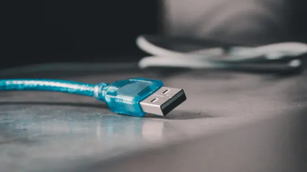
You often see usb ports on computers and devices. The usb3 pinout shows how each metal pin inside a usb connector connects and carries data or power. Look for the blue color on usb 3.0 connectors to spot them easily. Knowing the usb pinout helps you match devices and solve usb connection problems. Type A usb connectors fit most computers, while Type B usb connectors work with printers and other electronics. In electronic components and integrated circuits, the right usb pinout keeps data moving fast and safe.
- usb3 pinout answers how pins inside usb 3.0 connectors work.
- Blue color marks usb 3.0 for quick identification.
- Type A and Type B usb connectors serve different devices.
Key Takeaways
- USB 3.0 connectors are easily identified by their blue color, which indicates faster data transfer capabilities.
- Understanding the USB pinout helps you connect devices correctly and troubleshoot issues effectively.
- USB Type A connectors are used for host devices like computers, while Type B connectors are for peripheral devices like printers.
- The extra pins in USB 3.0 allow for simultaneous data transfer, significantly increasing speed compared to USB 2.0.
- Always check the pinout and connector type before connecting devices to avoid damage and ensure optimal performance.
USB Connectors Overview
When you work with electronic components and integrated circuits, you often use usb connectors to link devices. You see usb connectors everywhere, from computers to printers. Understanding the differences between usb connectors helps you choose the right one for your project and keeps your data safe.
USB Type A
You find usb Type A connectors on many host devices. These usb connectors look flat and rectangular. You plug them into desktops, laptops, and tablets. You also use them with video game consoles, smart televisions, and streaming players. Many home audio receivers and DVD players use usb connectors of Type A. You connect usb keyboards, mice, joysticks, and flash drives with these usb connectors.
- Desktops
- Laptops
- Netbooks
- Tablets
- Video game consoles
- Home audio/video receivers
- Smart televisions
- DVRs
- Streaming players
- DVD and Blu-ray players
- USB keyboards
- USB mice
- USB joysticks
- Flash drives
You see usb connectors with a blue color when they support usb 3.0. This color-coding helps you spot faster usb connectors. You get higher speeds and better performance with usb 3.0. The table below shows how color helps you identify usb connectors:
| Standard | Name | Color | Introduction | max. Speed | Nominal Speed |
|---|---|---|---|---|---|
| USB 2.0 | Hi-Speed | Black | 2011 | 40 MB/s | 480 Mbit/s |
| USB 3.0 | SuperSpeed | Blue | 2011 | 300 MB/s | 5000 Mbit/s |
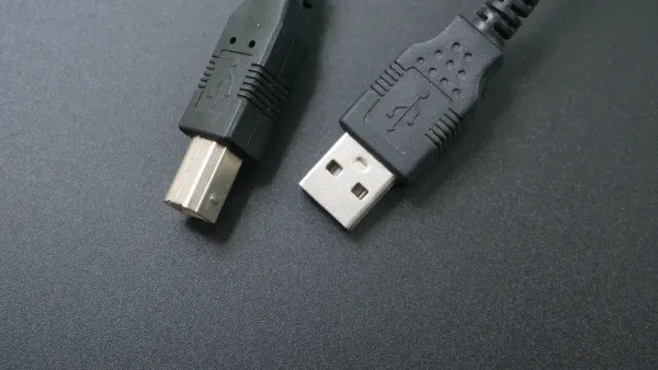
USB Type B
You use usb Type B connectors with peripheral devices. These usb connectors look square. You find them on printers and other electronics. When you connect usb Type B to integrated circuits, you transfer data between your computer and the device. You see usb connectors of Type B in many lab setups and electronic projects.
The table below shows the main physical differences between usb connectors:
| Connector Type | Shape | Design Purpose |
|---|---|---|
| USB Type A | Flat and rectangular | Host connections |
| USB Type B | Primarily square | Peripheral devices |
Tip: Always check the shape and color of usb connectors before connecting. This helps you avoid mistakes and keeps your electronic components safe.
You use usb connectors every day. Knowing how usb connectors work helps you build better electronic circuits and troubleshoot problems quickly.
USB3 Pinout and Configuration
When you work with electronic components and integrated circuits, you often need to understand how each usb pinout works. The usb3 pinout gives you a clear map of how signals and power flow through a usb connector. You can use a usb pinout diagram to see the exact arrangement of pins. This helps you connect devices safely and troubleshoot problems in your circuits.
USB3 Pinout Diagram
A usb pinout diagram shows you the layout of each pin inside a usb connector. You can use this diagram to match the right wires and signals when you build or repair circuits. The usb3 pinout adds more pins compared to older versions. This change allows for faster data transfer and better performance in your electronic projects.
Tip: Always check the usb pinout diagram before connecting a usb cable to your circuit. This step helps you avoid mistakes and keeps your components safe.
Here is a table that shows the standard pinout for usb 3.0 type-a and type-b connectors:
| Pin | Name | Direction | Color | Description |
|---|---|---|---|---|
| 1 | VBUS | red | +5 V power | |
| 2 | D- | ←→ | white | USB 2.0 Data - |
| 3 | D+ | ←→ | green | USB 2.0 Data + |
| 4 | GND | black | Ground | |
| 5 | StdA_SSRX- | ← | blue | SuperSpeed receiver |
| 6 | StdA_SSRX+ | ← | yellow | SuperSpeed receiver |
| 7 | GND_DRAIN | ground | Ground | |
| 8 | StdA_SSTX- | → | purple | SuperSpeed transmitter |
| 9 | StdA_SSTX+ | → | orange | SuperSpeed transmitter |
| Pin | Name | Direction | Color | Description |
|---|---|---|---|---|
| 1 | VBUS | red | +5 V power | |
| 2 | D- | ←→ | white | USB 2.0 Data - |
| 3 | D+ | ←→ | green | USB 2.0 Data + |
| 4 | GND | black | Ground | |
| 5 | StdB_SSTX- | → | blue | SuperSpeed transmitter |
| 6 | StdB_SSTX+ | → | yellow | SuperSpeed transmitter |
| 7 | GND_DRAIN | ground | Ground | |
| 8 | StdB_SSRX- | ← | purple | SuperSpeed receiver |
| 9 | StdB_SSRX+ | ← | orange | SuperSpeed receiver |
You can see from the diagram that usb3 pinout uses nine pins. This is more than the four pins found in older usb connectors. The extra pins allow for faster and more reliable data transfer in your integrated circuits.
Type A Pinout
The type-a connector is the most common usb connector you see on computers and many other devices. When you look at the usb3 pinout for a type-a connector, you notice it has nine pins. The older usb 2.0 type-a connector only has four pins. The extra five pins in usb 3.0 make a big difference in how your devices communicate.
| Connector Type | Number of Pins |
|---|---|
| USB 2.0 Type A | 4 |
| USB 3.0 Type A | 9 |
The usb3 pinout for a type-a connector includes:
- Pin 1 (VBUS): Supplies +5 V power to your device.
- Pin 2 (D-): Carries usb 2.0 data (negative).
- Pin 3 (D+): Carries usb 2.0 data (positive).
- Pin 4 (GND): Provides ground for power return.
- Pin 5 (StdA_SSRX-): Receives SuperSpeed data (negative).
- Pin 6 (StdA_SSRX+): Receives SuperSpeed data (positive).
- Pin 7 (GND_DRAIN): Provides ground for signal return.
- Pin 8 (StdA_SSTX-): Sends SuperSpeed data (negative).
- Pin 9 (StdA_SSTX+): Sends SuperSpeed data (positive).
The type-a connector uses these extra pins to send and receive data at the same time. This feature is called full-duplex communication. You get much faster data transfer rates, up to 5 Gbps. This speed is over ten times faster than usb 2.0. When you design circuits with integrated circuits, this speed helps you move large files quickly and keeps your projects running smoothly.
Note: The blue color inside the type-a connector helps you spot usb 3.0 easily. Always use the correct usb pinout to avoid damaging your electronic components.
Type B Pinout
The type-b connector is common on printers, scanners, and other peripheral devices. The usb3 pinout for a type-b connector also uses nine pins. The arrangement is a bit different from the type-a connector, but the function is similar. You still get the benefits of faster data transfer and better performance in your circuits.
Here is the pinout for a usb 3.0 type-b connector:
| Pin | Name | Direction | Color | Description |
|---|---|---|---|---|
| 1 | VBUS | red | +5 V power | |
| 2 | D- | ←→ | white | USB 2.0 Data - |
| 3 | D+ | ←→ | green | USB 2.0 Data + |
| 4 | GND | black | Ground | |
| 5 | StdB_SSTX- | → | blue | SuperSpeed transmitter |
| 6 | StdB_SSTX+ | → | yellow | SuperSpeed transmitter |
| 7 | GND_DRAIN | ground | Ground | |
| 8 | StdB_SSRX- | ← | purple | SuperSpeed receiver |
| 9 | StdB_SSRX+ | ← | orange | SuperSpeed receiver |
The type-b connector uses the extra pins for SuperSpeed data lines. You can send and receive data at the same time, just like with the type-a connector. This feature is important when you work with integrated circuits that need fast and reliable data transfer.
Reminder: Always check the usb pinout before connecting a type-b connector to your device. This step protects your circuits and ensures everything works as expected.
You now see how the usb3 pinout and the extra pins in both type-a and type-b connectors help you achieve faster data transfer. When you use the correct usb pinout, you keep your electronic components safe and your integrated circuits running at top speed.
Comparing USB Pinout Differences
Pin Arrangement
When you work with electronic components and integrated circuits, you need to understand how the pin arrangement affects your projects. The usb pinout for each version changes how signals move between devices. You see that usb 2.0 connectors use only four pins. Two pins supply power, and two pins handle data transfer. In contrast, usb 3.0 connectors add extra pins for faster data transfer and better performance.
Here is a table that shows the difference in pin arrangement:
| USB Version | Number of Pins | Configuration Description |
|---|---|---|
| USB 2.0 | 4 | Two for power, one pair for data |
| USB 3.0 | 6 | Four standard pins plus two extra pairs for 'superspeed' communication |
You notice that the usb 3.0 pinout includes more pins than usb 2.0. These extra pins allow for superspeed data transfer. When you use a type-b connector in your circuit, you must match the correct pinout to ensure safe operation. The extra pins in usb 3.0 do not interfere with older devices. You can still use a usb 2.0 device in a usb 3.0 port, but you will not get the higher data transfer speeds.
Tip: Always check the pinout before connecting a usb cable to your integrated circuit. This step helps prevent damage and ensures your project works as expected.
Data Transfer
The main reason for the extra pins in usb 3.0 is to boost data transfer rates. You get much faster speeds with usb 3.0 compared to usb 2.0. This improvement matters when you move large files or stream high-definition video in your electronic projects.
Here is a table that compares the maximum data transfer rates:
| USB Standard | Maximum Data Transfer Rate |
|---|---|
| USB 2.0 | 480 Mbps |
| USB 3.0 | 5 Gbps |
You see that usb 3.0 offers over ten times the data transfer speed of usb 2.0. This difference makes a big impact when you use usb in data-heavy applications. For example, when you connect a type-b connector to a printer or scanner, usb 3.0 lets you send large files quickly. In integrated circuits, this speed helps you process and store data without delays.
- USB 2.0: 480 Mbps
- USB 3.0: 5 Gbps
You also benefit from better power delivery with usb 3.0. This feature supports more demanding devices in your circuits. The improved shielding in usb 3.0 connectors protects your data transfer from interference, which is important in sensitive electronic components.
Note: If you connect a usb 3.0 device to a usb 2.0 port, the data transfer speed drops to usb 2.0 levels. You still get a working connection, but you lose the speed advantage.
Usage Scenarios
You use usb pinout knowledge in many practical situations. In electronic components and integrated circuits, you often need to choose the right usb connector for your project. The type-b connector is common in printers, scanners, and lab equipment. When you select a usb 3.0 type-b connector, you enable faster data transfer and better performance.
Here are some examples where usb 3.0 makes a difference:
| Device Type | Application Description |
|---|---|
| Smartphones and Tablets | Efficient internal data transfer |
| Gaming Consoles | Quick loading times and smooth gameplay |
| Data Centers | Rapid data movement within servers |
- Healthcare: You can access patient records and medical images quickly.
- Finance: You handle large financial transactions and data securely.
- Creative Fields: You transfer large media files for photography and video editing without delays.
You also see usb 3.0 used in HD video streaming and large data backups. These tasks require high data transfer rates, which the usb 3.0 pinout supports. When you design circuits with integrated circuits, you must consider the pinout and data transfer needs of your devices.
Reminder: Even though usb 3.0 and usb 2.0 connectors look similar, always check the pinout and compatibility. Some older devices may not work well with newer usb ports due to driver or BIOS issues.
You can rely on usb 3.0 for backward compatibility. If you use a usb 2.0 device in a usb 3.0 port, the connection works, but at the lower data transfer speed. The type-b connector in usb 3.0 is larger, so you can connect a usb 2.0 type-b plug, but not the other way around. This design helps protect your electronic components and integrated circuits from damage.
You now understand how usb pinout differences affect your projects. You can choose the right connector, plan for the best data transfer rates, and avoid common compatibility issues in your electronic circuits.
USB Troubleshooting Tips
Pinout Issues
When you work with electronic components and integrated circuits, you may face problems with usb pinout. Pinout issues can stop your devices from working as expected. You might see that your device is not recognized by your computer. Sometimes, the device does not receive power. This often happens when the VBUS or GND pins in your usb connectors are not connected correctly. Damaged cables or bent pins can also cause data transfer failures. If you use usb-a connectors or usb-b connectors, always check the pinout before connecting. A simple mistake in pinout can lead to connection problems or even damage your components.
Common pinout-related issues include:
- Device not recognized by the host system
- Device not receiving power
- Data transfer errors or connection failures
Tip: Always inspect your usb connectors for bent pins or debris before plugging them into your circuits.
You can use diagnostic tools to test your usb pinout and connectors. Tools like USB 3.0 Cable Modules, TRENDnet TC-NT3, and USB 3.0 Loopback Plugs help you check pin configurations and identify faults. These tools are useful when you design or repair electronic circuits that rely on usb connectors.
| Tool Name | Description |
|---|---|
| USB 3.0 Cable Modules | Automated testing and fault injection for usb cables |
| TRENDnet TC-NT3 | Tests pinout and finds faults in usb connectors up to 300 meters |
| USB 3.0 Loopback Plugs | Checks port function, measures voltage, and helps with stress testing |
Connectivity Problems
You may also face connectivity problems with usb connectors in your projects. These problems can slow down your work or stop your devices from communicating. To solve usb connectivity issues, follow these steps:
- Check all physical connections. Make sure your usb connectors and cables are not damaged.
- Restart your computer to clear temporary glitches.
- Open Device Manager and look for errors. Update or reinstall drivers if needed.
- Adjust power management settings to keep usb ports active.
- Update your operating system and drivers for better compatibility.
- Test for overloaded usb ports. Remove extra devices if needed.
- Check BIOS or UEFI settings to confirm usb ports are enabled.
- Try your usb device and cable on another computer to rule out hardware failure.
Note: Use high-quality usb cables and avoid using hubs when possible. This helps prevent bandwidth and power issues in your circuits.
Environmental factors like high temperatures can also affect usb connectors. Heat can slow down data transfer or damage cables. Handle your connectors gently to avoid physical wear. Electrical shorts, static discharge, and improper grounding can cause failures in your integrated circuits. Always follow best practices for routing and grounding when designing with usb connectors.
You learned how usb connector type affects electronic components and integrated circuits. Each type supports different devices and usb power delivery needs. The table below highlights key features:
| Connector Type | Description | Key Features |
|---|---|---|
| USB-A | Host for computers and hubs | Rectangular, blue for usb 3.0, supports usb power delivery |
| USB-B | Peripheral devices | Bulky, used for printers, strong usb power delivery |
| USB-Mini | Portable devices | Small, less common, limited usb power delivery |
| USB-Micro | Compact electronics | Fifth pin for signaling, supports usb power delivery |
- You select the right usb type for optimal data transfer and power delivery.
- Understanding usb pinout helps you troubleshoot and match usb power delivery to your circuit.
- Use usb pinout diagrams to visualize type and usb power delivery connections.
Remember: Knowing usb type and usb power delivery ensures your integrated circuits work safely and efficiently.
FAQ
What makes USB connector types important in electronic components?
You choose the right connector for your project to match host devices and peripheral equipment. Each connector supports specific transfer speeds and power needs. Using the correct connector type keeps your integrated circuits safe and ensures reliable data transfer.
Tip: Always check connector shape before connecting to avoid damage.
How does a USB 3.0 pinout improve data transfer in integrated circuits?
You get faster transfer rates because USB 3.0 pinout adds extra pins. These pins allow simultaneous sending and receiving of data. Your host device and peripheral communicate quickly, which helps electronic components process large files without delays.
Why do some connectors have a reversible design?
You use reversible connectors to simplify connections. Reversible USB and USB 3.1 C cable let you plug in either way. This feature reduces wear on electronic components and integrated circuits. You avoid mistakes and save time during assembly.
| Connector | Reversible | Common Use |
|---|---|---|
| USB Type-C | Yes | Host and peripheral devices |
| USB 3.0 micro-B cable | No | Peripheral devices |
How do you troubleshoot transfer problems with USB connectors?
You inspect each connector for bent pins or debris. You test cables with diagnostic tools. You check host and peripheral compatibility. You verify pinout matches your integrated circuits. You replace faulty cables to restore transfer speed and protect your components.
Can you use a USB 2.0 connector in a USB 3.0 port for electronic projects?
You can connect a USB 2.0 device to a USB 3.0 port. The host and peripheral will work together, but transfer speed drops to USB 2.0 levels. Your integrated circuits remain safe, but you lose the benefits of faster transfer.
Note: Always match connector type for best performance.