How Stators and Rotors Work with Electronic Components
The motor stator and rotor work together to convert electricity into motion. Electronic components control current timing to keep the rotor spinning.

A motor stator and rotor work as a team. The stator creates a magnetic field. The rotor responds to that field and spins. Electronic components switch and time the current so the rotor keeps turning. Think of these electronics as traffic controllers. They decide when and where current flows. An electric motor uses this teamwork to convert electrical energy into mechanical motion. Electric motor-driven systems account for approximately 30% of global electricity demand, so this process matters everywhere.

By the end, you will understand each part and how the stator and the rotor join electronics to form one working system.
Key Takeaways
- Stator creates a magnetic field. Rotor follows that field. Electronics switch current timing to keep rotor spinning.
- Brushed motors use commutators and brushes to reverse current direction. Brushless motors use electronic controllers for smoother operation.
- Rotating magnetic field drives rotor motion. Rotor turns slightly slower than synchronous speed to maintain torque.
- Choose a controller with voltage and current ratings above the motor's specs. This prevents overheating and failure.
Motor Stator and Rotor Basics
Every electric motor relies on two central parts working in tandem. The motor stator and rotor form the foundation of this partnership. Understanding each one helps you see how motors convert electricity into motion.
The Stator
The stator is the stationary part of an electric motor. It stays fixed inside the motor housing while everything else moves around it. The function of a stator centers on creating a magnetic field. When current flows through insulated wire called windings, the stator core becomes an electromagnet. These windings connect directly to the electrical supply. Laminated silicon steel typically forms the stator core. This material channels the magnetic field and reduces energy loss. The stator usually sits outside the rotor and carries heavy insulation for safety.
The Rotor
The rotor is the rotating component mounted on a shaft that connects to a load. This rotating part of the motor spins in response to the magnetic field the stator produces. The rotor core holds either permanent magnets, conductive bars, or its own windings. A squirrel cage rotor uses aluminum or copper bars with end rings. A wound rotor carries three-phase windings with slip rings. The rotor is the rotating part of the motor that delivers mechanical motion to fans, pumps, or conveyor belts.
An air gap separates the stator and the rotor. This gap width significantly affects the motor's electrical characteristics. Magnetic force decreases with the square of the distance across this gap. A smaller gap reduces the magnetizing current needed to drive flux. Manufacturing tolerances limit how narrow the gap can be. The gap must stay within a 10% tolerance of the average to avoid electrical noise and unbalanced currents. Rotor runout should not exceed 5% of the average air gap.
How an Electric Motor Creates Motion

Magnetic Attraction and Repulsion
The stator winding channels electromagnetic energy into the rotor to make the motor turn. A magnetic circuit forms between the stator core and the rotor core through the air gap. Permanent magnets induce a magnetic field that crosses the gap. This field enters the stator tooth core. Flux then flows through the tooth core and around through adjacent magnets and the rotor back iron, completing the circuit. Torque generates when flux lines from the tooth face interact with the rotor magnets. Coil windings around the tooth experience changing flux from this circuit. This induces back EMF and contributes to torque. The magnetic field strength at the air gap directly affects torque output.
According to Faraday's Law, a changing magnetic field within a closed loop induces an electromotive force driving current flow. In the electric motor, this induced current interacts with the magnetic field to produce work. The motor stator and rotor work together to convert electrical energy into mechanical motion. This process forms the foundation of every electric motor you use.
Fleming's left-hand rule predicts force direction. Your thumb shows force direction. Your forefinger shows magnetic field direction from North to South. Your middle finger shows current direction from Positive to Negative. These three directions are perpendicular. Current flows in opposite directions on each coil side in a motor. One side pushes up while the other pushes down. This creates rotation.
The core principle of motor operation relies on this interaction of magnetic fields. The stator creates one magnetic field. The rotor responds to it. These two components work as a team. The interaction of these two components produces the force you need. Without it, the motor cannot turn.
Why the Rotor Keeps Spinning
The rotor keeps spinning because the magnetic field from the stator continuously shifts position. In a three-phase motor, stator windings receive three sine waves 120 degrees out of phase. Adding them produces a single rotating vector with constant magnitude. This creates a rotating magnetic field.
Imagine lights arranged in a circle pointing down with overlapping coverage. Instead of turning them on and off, you dim and brighten them in sequence. The brightest floor point moves continuously around the circle. The stator's rotating magnetic field works the same way. Its north pole moves toward the stator's south pole. This attraction drives it to follow the rotating magnetic field. This interaction of magnetic fields keeps it turning.
In induction motors, it has short-circuited turns. These develop eddy currents in the rotating field of the stator. Lorentz force then moves it. However, it cannot reach synchronous speed. Slip refers to the speed difference between synchronous speed and actual speed.
At zero slip, no rotor EMF is induced and no induction-motor torque is produced.
The rotor must turn slightly slower than synchronous speed to allow induction and torque generation. You calculate slip as a percentage. S equals the difference between synchronous speed and the actual speed divided by synchronous speed times 100.
Electronic components control current switching timing. They ensure the rotating field continues ahead of the rotor. This keeps it chasing the field. The stator and the rotor maintain their partnership through this cycle. The result is steady mechanical power you can use.
Electronic Components of a Motor

The components of a motor extend beyond metal and wire. Electronic parts decide when current flows and in which direction. These parts turn a simple magnetic interaction into controlled, continuous motion.
Commutators and Brushes
A brushed DC motor uses a mechanical switch to keep its rotor turning. The purpose of a commutator is to reverse current in the armature windings at the right moment. Here is how the cycle works:
- As the split ring commutator rotates, the carbon brushes make contact with alternating segments of the commutator ring.
- Momentum allows the brushes to slide past the gaps in the ring until making contact with the next segment.
- When contact switches from one segment to the next, the current flow through the armature loop switches directions.
- This causes the armature's magnetic field to switch polarity.
- The changing polarity causes the armature to rotate again in relation to the stator magnets.
- As long as the electrical circuit is connected, this cycle repeats continuously, causing the motor's rotation.
The commutator acts as a mechanical rectifier. It ensures the magnetic field in the rotor always pushes in the same rotational direction. A wire connected to the power supply feeds current into the brushes. A wire connected to the drive circuit carries it onward. The brushes and commutator change the direction of the electric current at precise points. This keeps torque consistent.
Brushes wear over time. Check them around the 500 to 1000 hour mark, depending on how hard the motor works. Replace brushes when worn down to 1/4 of original length. Carbon brush wear creates friction against the commutator. This leads to poor electrical connections and performance decline. Well-maintained motors can outlast poorly maintained counterparts by up to 50%.
Brushless Controllers
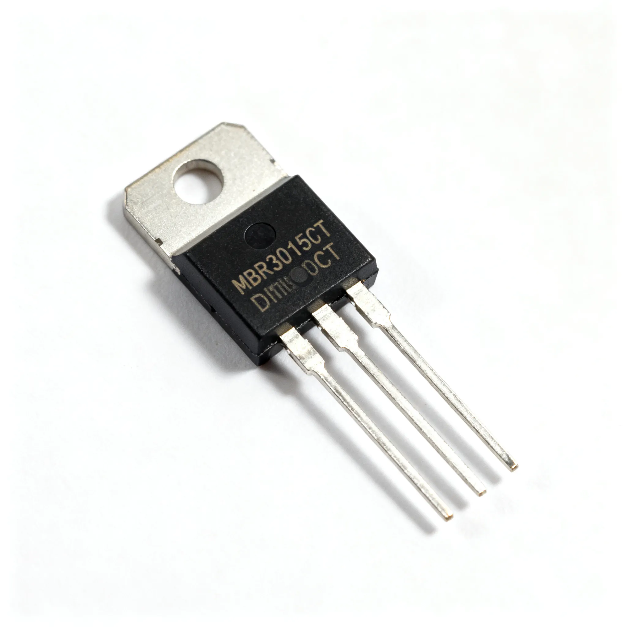
A brushless DC motor removes the brushes entirely. An electronic controller with semiconductor switches handles commutation instead. An ESC uses MOSFET transistors as fast electronic switches, turning them ON and OFF roughly 2000 times per second. By adjusting the ratio of ON time to OFF time, the ESC varies average power delivered to the motor. When a MOSFET switches ON, current through the motor coils increases and magnetic flux builds up. When it switches OFF, a diode channels stored energy back as current.
This electronic approach eliminates mechanical wear from commutation. Sensors and control circuits manage current flow at the right time to maintain consistent torque. Electrical power is delivered optimally, which lowers consumption and reduces heat. The controller generates a rotating magnetic field by timing current in each phase. Trapezoidal control uses stepped waveforms for lower smoothness. Sinusoidal control produces continuously varying voltages for smoother operation. Field-Oriented Control decouples torque-producing and flux-producing currents for the smoothest performance.
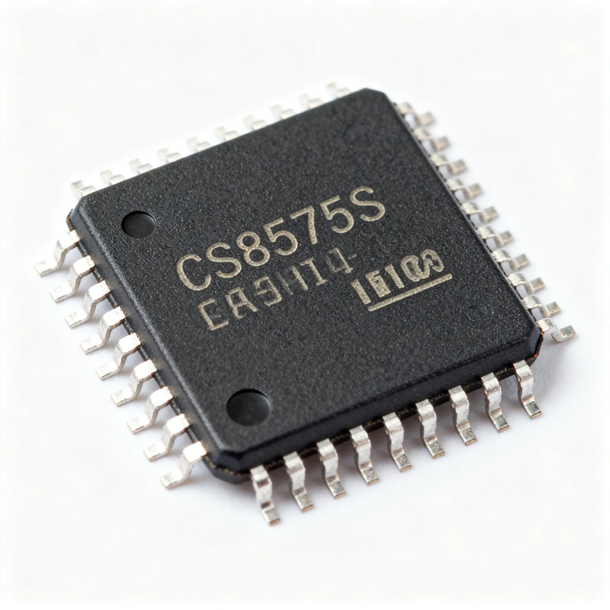
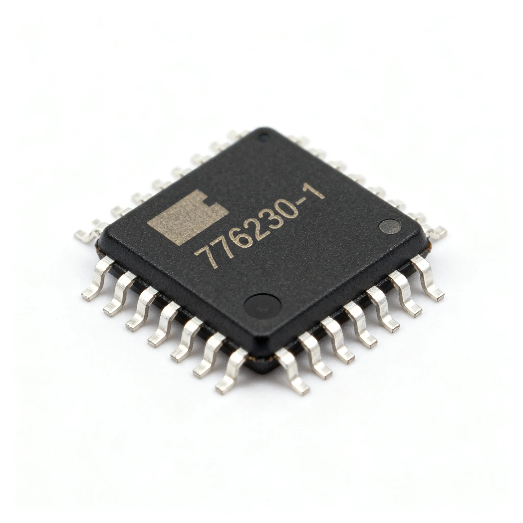
PWM switching frequency affects motor smoothness. Small low-voltage motors typically use 10 to 25 kHz. Drone ESCs commonly use around 30 to 50 kHz to reduce torque ripple. Frequencies below roughly 10 to 15 kHz can produce audible whine. Keeping switching above 15 kHz helps avoid audible noise. Nova Technology Company (HK) Limited, a HiSilicon-designated (authorized) solutions partner, provides chip-level solutions for these controllers. Their integrated circuits combine driver, control, and protection functions for brushless motor applications.
Both systems manage the same two things: current direction and field timing. The brushed motor does it mechanically. The brushless motor does it electronically. Each approach keeps the rotor chasing the rotating magnetic field.
Stator, Rotor, and Electronics Together
Matching Electronics to Motor Type
You cannot pair any controller with any motor and expect good results. The controller must match the motor across several key parameters. Voltage ratings need headroom. A driver voltage range should sit roughly 20 to 30 percent above the motor's rated voltage to handle transients and regenerative events. Current ratings matter too. The driver's continuous rating should reach at least 1.2 times the motor's rated current, while its peak rating must handle 2 to 3 times that value during startup.
The controller also needs to know where the rotor sits at every moment. Hall effect sensors provide real-time feedback about rotor position. This feedback lets the controller time the energizing of the stator windings correctly. Sensorless designs monitor back electromotive force instead. Either way, the controller must determine which winding to energize next. This keeps the magnetic field leading the rotor by a specific angle. The core principle of motor operation depends on this timing.
Why Integration Matters
When the motor stator and rotor work with properly matched electronics, energy losses drop. Precision manufacturing reduces the air gap, which minimizes resistance and increases flux linkage. Copper windings and rotor bars offer higher conductivity than aluminum, cutting resistive losses further. Companies like General Motors design the motor, inverter, and gearbox as one system. This tight integration gives precise control over performance and thermal behavior.
Mismatched components create real problems. Voltage imbalance across three-phase systems causes excessive current in one phase, raising operating temperatures and risking insulation breakdown. Shaft voltage can exceed the insulating capability of bearing grease, leading to bearing pitting and destruction within months. You avoid these failures by matching electronics to the electric motor carefully.

Understanding this relationship helps you choose the right components, troubleshoot faults faster, and appreciate the motors inside everyday devices.
The stator, rotor, and electronics form one coordinated unit. The stator builds a magnetic field. The rotor chases that field. Electronic components switch current direction and time each pulse. This teamwork turns magnetic attraction into controlled motion. You see this in every electric motor around you.
Understanding this relationship pays off. You can choose the right motor for a job. You can spot faults faster when a rotor stalls or a controller misfires. You can also appreciate the hidden engineering inside fans, pumps, and vehicles. The magnetic field, the spinning rotor, and the timing circuits all depend on each other. That partnership delivers the motion you rely on every day.
FAQ
How do I know when to replace motor brushes?
Check brush length when the motor reaches 500 to 1000 hours of use. Replace brushes when worn to 1/4 of original length. Worn brushes cause poor electrical contact and reduce performance.
Why does the air gap between the stator and rotor matter so much?
Magnetic force drops with the square of the gap distance. A larger gap raises the magnetizing current needed. The gap must stay within a 10% tolerance to avoid electrical noise and unbalanced currents.
What causes a brushless motor to whine during operation?
The whine comes from the PWM switching frequency. The controller must know the rotor position to time current correctly. Frequency below 10 to 15 kHz produces an audible whine. Most drone ESCs operate around 30 to 50 kHz to avoid this.
What happens if I pair the wrong controller with a motor?
The motor may overheat or fail. Voltage imbalance causes excessive current in one phase. Shaft voltage can damage bearings within months. Choose a controller rated 20 to 30 percent above the motor voltage.