Checking Continuity Multimeter Basics for 2026
Checking continuity multimeter steps ensure safe, accurate fault detection in wires, switches, and circuits for reliable electrical troubleshooting.
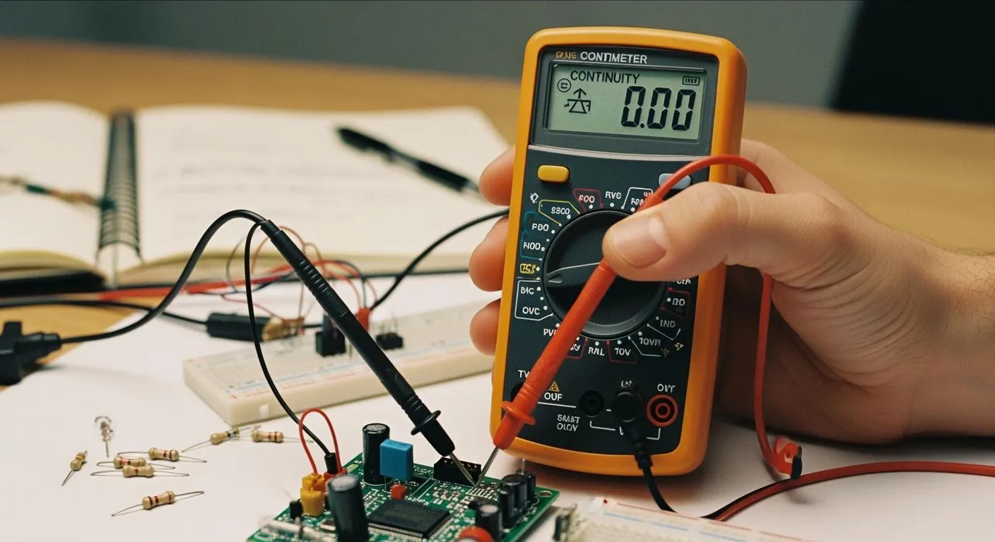
You can check continuity easily with a multimeter. Imagine you need to find out if a wire in your home or workshop actually connects from one end to the other. Grab your multimeter, set it to continuity mode, and touch the probes to each end of the wire. This simple action helps you spot broken wires, faulty connections, or damaged circuits. Continuity testing protects you and your equipment by ensuring effective grounding and secure electrical connections.
- It prevents electrical shocks and equipment failures.
- Faulty electrical equipment causes about 13% of home fires, so regular testing is vital.
With the right steps, checking continuity multimeter functions becomes a straightforward task for anyone.
Key Takeaways
- Use a multimeter in continuity mode to check if electricity flows through a wire. This helps identify broken connections.
- Regular continuity testing prevents electrical hazards and equipment failures, reducing the risk of home fires.
- Always power off the circuit before testing continuity to ensure safety and avoid damaging your multimeter.
- A continuous beep from the multimeter indicates good continuity, while no beep means a break or fault exists.
- Follow safety precautions, like using insulated tools and verifying the tester's functionality, to protect yourself during testing.
Continuity Meaning & Importance
What Is Continuity
You often hear the term continuity when working with electrical circuits. In simple terms, continuity means that electricity can flow smoothly from one point to another without interruption. When you test for continuity, you check if a path exists for current to travel. If the path is complete, the circuit is continuous. If there is a break, the circuit is open and electricity cannot flow.
- A continuity test confirms that current can flow in an electrical circuit, showing the circuit is continuous.
- The test works by applying a small voltage across two or more points in the circuit to check for current flow.
Tip: You can use a multimeter to perform this test quickly and safely. This tool helps you find broken wires or faulty connections before they cause bigger problems.
Why Continuity Matters
You need to check continuity for many reasons. It helps you find faults in wires, switches, and other components. In electronics, you use continuity testing to verify the integrity of printed circuit boards, wires, and parts. Automotive engineers rely on it to diagnose issues in wiring harnesses and electrical systems. In telecommunications, you use it to ensure data cables and connections work as expected.
- You can check wiring integrity, test fuses, and switches.
- You can identify broken wires or connections in many electrical devices.
Continuity testing also keeps you safe. It identifies breaks and faults in circuits, which helps prevent malfunctions. By making sure circuits are complete, you reduce the risk of unsafe conditions. This method is a primary way to detect issues that could compromise safety. It plays a big role in electrical diagnostics and maintenance.
Note: Regular continuity checks help you avoid electrical hazards and keep your equipment running smoothly.
Multimeter Basics for Continuity Test

Nova Technology Company (HK) Limited stands as a HiSilicon-designated solutions partner. You can rely on their expertise in chip-level solutions and system integration. Their work supports advanced applications in the semiconductor industry, including smart devices, industrial automation, and IoT systems. When you use a multimeter for a continuity test, you benefit from innovations that companies like Nova Technology Company (HK) Limited bring to the market.
Key Parts & Symbols
You need to know the main parts of a multimeter before you start a continuity test. The display shows readings. The rotary dial lets you select the continuity function. You use two probes, usually black and red, to connect to the circuit. The continuity function often appears as a symbol that looks like a sound wave or diode.
Here is a quick reference table for common multimeter symbols:
| Symbol | Meaning |
|---|---|
| Ω | Resistance |
| 🔊 or Diode | Continuity function |
| V | Voltage |
| A | Current |
Tip: Always check your multimeter manual for the exact continuity function symbol. Manufacturers sometimes use different icons.
You must insert the probes into the correct ports. The black probe goes into the COM port. The red probe fits into the port marked for continuity or resistance.
Setting to Continuity Mode
You set your multimeter to the continuity function by turning the rotary dial to the correct symbol. Most digital multimeters beep when you select the continuity function. You should hear a sound or see a symbol on the display.
Follow these steps for a continuity test:
- Insert the probes into the correct ports.
- Turn the dial to the continuity function.
- Confirm the display shows the continuity symbol.
- Touch the probes together. The multimeter should beep or show a low resistance value.
Note: If your multimeter does not beep, check the manual. Some models only show numbers during a continuity test.
You use the continuity function to check wires, switches, and circuit paths. You can test many electrical components with a multimeter. The continuity test helps you find breaks or faults quickly. You should always use the continuity function before working on any electrical project.
A multimeter makes the continuity test simple and safe. You can trust your results when you follow these steps. The continuity function is one of the most important features for troubleshooting.
Checking Continuity Multimeter Steps

Preparation & Safety
You need to prepare before you start checking continuity multimeter functions. Gather the right tools and equipment for a safe and accurate continuity test. You can use a multimeter, a dedicated circuit continuity tester, or specialized tools for advanced continuity measurements. Here is a quick reference table for your toolkit:
| Tool Type | Description |
|---|---|
| Multimeters | Versatile tool for measuring voltage, current, and resistance, often includes a continuity mode. |
| Dedicated Circuit Continuity Testers | Simpler, affordable devices specifically for checking electrical paths, usually with a light or buzzer. |
| Specialized Tools | Advanced tools like oscilloscopes or cable testers for diagnosing issues in complex circuits. |
Safety comes first when you perform a continuity test. You must follow these precautions to protect yourself and your equipment:
| Safety Precaution |
|---|
| Ensure the circuit is powered off |
| Use insulated tools |
| Verify the tester is working |
| Avoid touching probe tips during testing |
Tip: Always turn off the circuit before checking continuity multimeter readings. Insulated tools help prevent accidental shocks. Test your multimeter by touching the probes together. You should hear a beep or see a low resistance value.
Performing the Continuity Test
You can start the continuity test after you prepare your tools and follow safety steps. Checking continuity multimeter procedures is simple if you follow these steps:
- Set your multimeter to continuity mode. Look for the diode or sound wave symbol.
- Insert the black probe into the COM port and the red probe into the continuity port.
- Confirm the circuit is powered off. Check for zero voltage.
- Test your multimeter by touching the probe tips together. You should hear a beep or see a low resistance value.
- Place one probe at each end of the wire, switch, or component you want to test. Make sure the component is isolated from the circuit.
- Connect the test leads across the area you want to check. The position of the probes does not matter, but you must ensure the component is not connected to other parts.
- Observe the display and listen for a beep.
Note: A continuous beep means the wire or component has continuity. No beep means there is a break or fault. You can use continuity testing to check switches, fuses, and circuit paths. Testing components with a multimeter helps you find faults quickly.
Reading Results
You must interpret the readings from your multimeter to understand the continuity test results. The display and sound signals tell you if the circuit is complete or broken. Here is a table to help you decode the readings:
| Reading | Meaning |
|---|---|
| OL | Indicates an open circuit with no continuity. |
| 1 | Indicates good continuity. |
| < 10Ω | Suggests a low resistance path, confirming that the circuit is closed and current can flow. |
You can also use sound signals to check continuity. A continuous beep means the circuit is closed and current can flow. If you do not hear a beep, the circuit is open or broken. You must understand these signals to troubleshoot and ensure safety.
- A continuous beep means the wire has continuity and the path is complete.
- No beep means there is a break or fault in the wire or component.
Callout: Always check continuity measurements before you repair or replace electrical parts. You can prevent equipment failures and electrical hazards by using a multimeter for continuity testing.
Checking continuity multimeter steps help you find faults and confirm safe connections. You can use these steps for wires, switches, and circuit paths. You must always follow safety precautions and interpret the results carefully. Continuity testing is a key skill for anyone working with electrical systems.
Troubleshooting & Tips
No Continuity Solutions
You may face a situation where your continuity test shows no continuity in a circuit. You can solve this problem by following a few simple steps. First, use a digital multimeter to check for continuity. Activate the audible continuity mode to make the process easier. If the circuit layout makes testing difficult, use a long wire to create a return path for your continuity test.
- Select the correct mode on your multimeter for continuity testing.
- Connect the test leads to the circuit component you want to test.
- Turn the dial to the continuity test mode.
- Attach the black lead to the COM jack and the red lead to the VΩ jack.
- Make sure the circuit is de-energized before you connect the test leads across the component.
You should interpret the results based on whether your multimeter emits a beep or not. If you hear no beep, you need to investigate further. Common causes include loose connections, damaged components, physical damage, or corrosion.
| Type of Fault | Description |
|---|---|
| Open Circuit Faults | Prevent current from flowing through a circuit. |
| Short Circuit Faults | Cause abnormal flow of current in a circuit. |
If your continuity tester does not indicate continuity, it suggests a break or fault in the wire. Physical damage, corrosion, or loose connections often cause these issues.
Common Mistakes
You can avoid mistakes during a continuity test by following best practices. Many people forget to remove the battery from the circuit, which wastes time on problems that do not exist. Failing to isolate the component from others can result in inaccurate readings. Loose connections, dirty probes, or damaged components may cause no beep, false readings, or intermittent continuity.
Trying to measure resistance on a live circuit invalidates the reading. Always make sure the circuit is powered off before you use the multimeter for a continuity test.
Safety Reminders
You must follow safety reminders to protect yourself during a continuity test. Electrical safety organizations recommend these practices:
| Safety Reminder | Description |
|---|---|
| Use Proper PPE | Always use properly rated personal protective equipment when working on or near live equipment. |
| Adhere to Lockout/Tagout Procedures | Never bypass lockout/tagout procedures to ensure safety during maintenance and testing. |
| Inspect Equipment Regularly | Regularly inspect cables, plugs, and tools, replacing any damaged items immediately. |
| Maintain Safe Distances | Keep a safe distance from overhead and underground power lines to avoid hazards. |
| Only Qualified Personnel Should Work | Ensure that only qualified individuals perform electrical work to minimize risks. |
| Grounding is Essential | Proper grounding prevents static sparks and protects workers from electric shocks. |
| Verify Continuity Before Operations | Always verify continuity before starting any electrical operations to ensure safety. |
| Regular System Inspections | Conduct regular inspections of grounding systems to maintain safety standards. |
You should always verify continuity before you start any electrical operation. Regular inspections and proper grounding help you maintain safe conditions. You can prevent accidents and equipment failures by following these safety tips during every continuity test with your multimeter. Troubleshooting circuits becomes easier when you use these guidelines.
You can check continuity with a multimeter by following these steps:
- Power off the system and check continuity between VCC and GND.
- Confirm correct wiring to the microcontroller and devices.
- If all checks pass, use serial debugging or a logic analyzer.
Understanding continuity test results helps you find faults quickly, reduce downtime, and prevent hazards. Practice using your multimeter for continuity tests to build confidence. For advanced features, explore resources like A Guide to Continuity Testing with a Multimeter and How to Use a Multimeter: A Comprehensive Guide.
FAQ
How do you know if a wire has continuity?
You check for continuity by using a multimeter in continuity mode. Place the probes on both ends of the wire. If you hear a beep or see a low resistance value, the wire has continuity.
Can you test continuity with power on?
You should never test continuity with power on. Always turn off the circuit before testing. Testing continuity on a live circuit can damage your multimeter and put you at risk of electric shock.
What does “OL” mean on a continuity test?
“OL” stands for “open loop.” This means there is no continuity in the circuit. The path is broken, and electricity cannot flow. You need to check for damaged wires or faulty connections.
Why is continuity important in electronics?
Continuity ensures that current can flow through a circuit without interruption. You use continuity tests to find breaks, faulty switches, or poor connections. This keeps your devices safe and working properly.
What should you do if there is no continuity?
If you find no continuity, inspect the wire or component for damage. Clean any corrosion from contacts. Replace broken parts if needed. Continuity testing helps you locate and fix electrical problems quickly.