Potentiometer schematic explained for everyday electronics
Potentiometer schematic details, terminal functions, and symbol meanings explained for practical electronics troubleshooting and design.
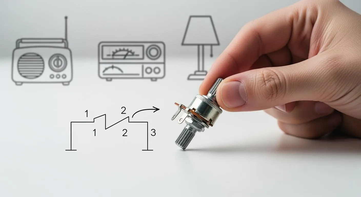
A potentiometer schematic shows how a potentiometer works inside a circuit. You see this symbol in almost every electronics project that needs variable resistance, voltage division, or signal tuning. The schematic usually features a three-terminal resistor with a wiper that moves to control voltage or current. If you understand these diagrams, you can spot problems and predict how circuits will behave. By reading schematics, you also learn to communicate your ideas to others who build or fix electronics.
Key Takeaways
- A potentiometer schematic features a unique symbol with an arrow, indicating the adjustable wiper. This helps you identify how to control voltage or resistance in a circuit.
- Understanding the three terminals of a potentiometer is crucial. The outer terminals connect to voltage and ground, while the wiper provides an adjustable output.
- To read a potentiometer schematic, locate the resistive element, identify the wiper, and check the connections. This skill helps you predict circuit behavior and troubleshoot issues.
- Different types of potentiometers, like rotary and slide, have distinct symbols. Knowing these helps you choose the right component for your electronics projects.
- When working with potentiometers, always check the schematic for resistance values and wiring configurations to ensure proper functionality and avoid errors.
Potentiometer schematic basics

Schematic symbol overview
When you look at a potentiometer schematic, you notice a unique symbol that tells you a lot about how the component works. The symbol always shows a resistor with an arrow pointing to it. This arrow represents the adjustable part of the potentiometer, called the wiper. The way the resistor looks in the schematic can change depending on where you live or what standard you follow.
Here is a table that shows the differences:
| Region | Symbol Representation |
|---|---|
| American | Zig-zag representation of a resistor |
| European | Rectangular box representation of a resistor |
| Both | Resistor symbol with an arrow indicating a variable resistor |
You see the arrow in both American and European schematics. The arrow points to the middle of the resistor, showing that you can adjust the resistance. This symbol helps you quickly spot a potentiometer in any circuit diagram.
Tip: When you read a potentiometer schematic, always look for the arrow. It tells you which part of the component you can move to change the voltage or resistance.
Key parts and terminals
A potentiometer has three main terminals. Each one plays a special role in how the device works inside a circuit. You can see their functions in the table below:
| Terminal | Function |
|---|---|
| Outer terminal 1 | Ground |
| Wiper | Adjustable output |
| Outer terminal 2 | Supply voltage |
- The two outer terminals connect to the ends of the resistive element. One usually goes to ground, and the other connects to the supply voltage.
- The middle terminal is the wiper. This part slides along the resistive path when you turn the knob or move the slider.
The wiper splits the resistor into two sections. When you move the wiper, you change the resistance on each side. This action divides the voltage between the two outer terminals. You get an adjustable output voltage at the wiper. This feature is why you use potentiometers for things like volume controls and brightness adjustments.
- The wiper acts as a movable contact that divides the resistive element into two parts.
- Adjusting the wiper changes the resistance ratio between the two segments.
- This change lets you control the output voltage smoothly.
When you understand how each terminal works in a potentiometer schematic, you can design circuits that need precise voltage control. You also find it easier to troubleshoot problems because you know what each part does.
Reading potentiometer schematic
Interpreting circuit diagrams
When you look at a circuit diagram, you often see a potentiometer schematic as part of the design. Reading this symbol helps you understand how the potentiometer controls voltage or resistance in the circuit. You can follow these steps to read a potentiometer schematic in any diagram:
- Find the resistive element. This part looks like a zigzag line in American schematics or a rectangular block in European ones.
- Look for the arrow that points to the resistor. This arrow shows the adjustable part, called the wiper.
- Notice the three terminals. Two connect to the ends of the resistive track, and one connects to the wiper.
- Check for terminal numbers. Sometimes, you see numbers like 1 and 3 for the fixed ends and 2 for the wiper.
- See how the potentiometer connects to other parts. The outer terminals usually connect to the input voltage and ground. The wiper connects to the output.
Tip: Always trace the arrow in the schematic. It tells you where the adjustable output comes from.
You can use this process to read potentiometer schematics in audio equipment, sensor circuits, or even robotics projects. Understanding the symbol helps you predict how turning the knob or moving the slider will change the circuit’s behavior.
Identifying connections
You need to know which terminal does what when you wire or troubleshoot a potentiometer. The schematic gives you clues:
- The two fixed terminals (often labeled 1 and 3) connect to the ends of the resistive element. You usually attach one to the supply voltage and the other to ground.
- The wiper (often labeled 2) is the movable terminal. This part slides along the resistive track and gives you an adjustable output voltage.
- In rotary potentiometers, the symbol may show a circular motion. In slide potentiometers, the symbol looks more linear.
- The American symbol uses a zigzag resistor with an arrow, while the European symbol uses a rectangle with an arc and arrow. Both show three terminals.
Here is a simple table to help you remember the connections:
| Terminal Number | Name | Typical Connection |
|---|---|---|
| 1 | Fixed End | Supply Voltage (Vcc) |
| 2 | Wiper | Output Signal |
| 3 | Fixed End | Ground (GND) |
When you see a potentiometer schematic in a circuit, you can quickly find the wiper and the two fixed ends. The input voltage goes to the fixed terminals, and the output comes from the wiper. This setup lets you adjust the voltage sent to other parts of the circuit.
Note: If you ever get confused, look for the arrow in the schematic. It always points to the wiper, which is the key to controlling the output.
By practicing these steps, you will get better at reading potentiometer schematics. You will also find it easier to design, build, and troubleshoot your own electronic projects.
Potentiometer types and symbols

Potentiometers come in several types, each with its own schematic symbol and application. You often see three main types in everyday electronics: rotary, slide, and trimmer potentiometers. Understanding their differences helps you read schematics and choose the right part for your project.
| Type of Potentiometer | Description | Schematic Symbol (ANSI) | Schematic Symbol (IEC) |
|---|---|---|---|
| Rotary | Uses a rotating knob to change resistance and output. | Zigzag with arrow (circular) | Rectangle with arrow (circular) |
| Slide | Uses a sliding contact for linear adjustment. | Zigzag with arrow (straight) | Rectangle with arrow (straight) |
| Trimmer | Adjusted with a tool for fine-tuning, not regular user control. | Zigzag with T-shape arrow | Rectangle with T-shape arrow |
Rotary potentiometer
You find rotary potentiometers in devices like audio mixers and radios. You turn a knob to adjust the resistance. The schematic symbol shows a resistor with an arrow pointing at it, often in a circular orientation. This arrow represents the wiper that moves as you rotate the shaft. Rotary potentiometers give you smooth, continuous control over voltage or current.
Tip: In schematics, the circular arrow helps you spot rotary potentiometers quickly.
Slide potentiometer
Slide potentiometers, also called linear potentiometers, use a slider instead of a knob. You move the slider along a straight path to change the resistance. The schematic symbol looks similar to the rotary type but shows a straight line for the motion. Slide potentiometers work well in graphic equalizers and lighting controls, where you need precise, linear adjustments.
- The symbol often appears as a resistor with a straight arrow.
- You can easily identify the direction of adjustment in the diagram.
Trimmer potentiometer
Trimmer potentiometers, or "trimmers," are small, adjustable resistors used for calibration. You adjust them with a screwdriver or special tool. The schematic symbol usually includes a T-shaped arrow, showing that you need a tool for adjustment. Trimmers often have numbers on their terminals: '1' and '3' for the ends, '2' for the wiper. You use trimmers for fine-tuning circuits, such as setting reference voltages or calibrating sensors.
| Feature | Description |
|---|---|
| Three-Terminal Device | Lets you set precise resistance values in a circuit. |
| Adjustment Mechanism | Top or side adjustment, depending on PCB layout. |
| Single-Turn/Multi-Turn | Single-turn for quick changes, multi-turn for high precision. |
Note: Trimmer potentiometers are not meant for frequent adjustments. Use them when you need to set a value and leave it.
By learning these types and their symbols, you can read schematics more confidently and select the right potentiometer for your electronics projects.
Potentiometer uses
You see potentiometers in many everyday electronics. They help you control sound, adjust sensors, and manage motor speed. When you read a potentiometer schematic, you can spot these uses in different devices.
Volume control
You often use a potentiometer to adjust the volume in audio equipment. When you turn the knob on a radio or speaker, you change the resistance. This action changes the voltage sent to the amplifier. The potentiometer schematic in these circuits usually shows the wiper connected to the audio signal path. The two fixed terminals connect to the input signal and ground. By moving the wiper, you can make the sound louder or softer.
Tip: If your speaker sounds scratchy, check the potentiometer for dust or wear. Cleaning or replacing it can fix the problem.
Sensor calibration
Potentiometers help you calibrate sensors in many devices. For example, you might use one to set the reference voltage in a temperature sensor circuit. The potentiometer schematic shows the wiper connected to the sensor’s input. By adjusting the potentiometer, you can fine-tune the sensor’s response. This feature is important in devices like thermostats, light meters, and even some medical equipment.
- You can use trimmer potentiometers for calibration.
- These are small and adjusted with a tool for precise settings.
Motor speed adjustment
You can control the speed of a DC motor using a potentiometer. In a typical circuit, the potentiometer adjusts the voltage that goes to a timer IC, such as the 555 timer. The output from the timer then controls a MOSFET, which switches the motor on and off very quickly. By turning the potentiometer, you change the pulse width sent to the MOSFET. This process lets you make the motor spin faster or slower.
- Pressing a switch activates the speed control.
- Moving the potentiometer changes the motor speed smoothly.
You find this setup in fans, model cars, and robotics projects. Reading the potentiometer schematic helps you understand how each part connects and works together.
Practical potentiometer tips
When you work with potentiometers in electronics, you want reliable results and smooth adjustments. Choosing the right part, wiring it correctly, and solving common problems will help your projects succeed. In the world of advanced electronics, companies like Nova Technology Company (HK) Limited play a key role. As a HiSilicon-designated solutions partner, Nova Technology Company specializes in chip-level solutions and system integration for the IC industry. You see their expertise in applications such as smart devices, industrial automation, and high-performance embedded systems.
Choosing the right potentiometer
You need to match the potentiometer to your project’s requirements. Consider these important factors:
| Factor | Description |
|---|---|
| Resistance Value | Controls the range of adjustment; common values are 1kΩ to 10kΩ. |
| Taper Type | Determines how resistance changes; options include linear, audio, and logarithmic. |
| Length and Form Factor | Must fit your device’s physical space and control needs. |
| Mounting Style | Choose between surface mount and through-hole for best fit on your circuit board. |
| Operating Temperature Range | Pick a potentiometer that works well in your device’s environment. |
Tip: Always check the schematic for the recommended resistance value and taper type before you buy.
Wiring advice
You can wire a potentiometer in different ways, depending on your circuit’s needs. The schematic will show you the best configuration.
| Configuration Type | Connection Details |
|---|---|
| Voltage Divider | Pin 1 → VCC; Pin 3 → GND; Pin 2 (Wiper) → Output (variable voltage). |
| Variable Resistor (Rheostat) | Pin 1 → VCC; Pin 2 (Wiper) → Load; Pin 3 left unconnected. |
- Identify the wiper and end pins with a multimeter before soldering.
- Mixing up terminals can cause the circuit to malfunction.
Note: Always double-check your wiring against the schematic to avoid errors.
Troubleshooting
If your potentiometer does not work as expected, follow these steps:
- Inspect for mechanical issues like binding or excessive play. Clean and lubricate if needed.
- Check for erratic resistance readings. Clean contacts or replace the potentiometer if damaged.
- Test for control issues by verifying signal integrity and checking for damaged components.
- After repairs, test the potentiometer through its full range to confirm smooth operation.
Common problems include erratic readings, dead spots, and calibration drift. Careful inspection and testing will help you restore proper function.
🛠️ Good troubleshooting skills make your electronics projects more reliable and enjoyable.
Understanding potentiometer schematics gives you a strong foundation for building and fixing electronics. You can read circuit diagrams, choose the right parts, and solve problems with confidence.
- Try experimenting with different potentiometers in your own projects.
- Practice reading schematics to sharpen your skills.
Remember, every project you build helps you learn more. Stay curious and keep exploring electronics!
FAQ
What does the arrow on a potentiometer schematic mean?
The arrow shows the wiper. You move this part to adjust the resistance. The wiper lets you control the output voltage or signal in your circuit.
Can I use a potentiometer as a simple variable resistor?
Yes, you can. Connect one end terminal and the wiper. Leave the other end terminal unconnected. This setup creates a variable resistor, also called a rheostat.
How do I know which terminal is the wiper?
Look for the terminal with the arrow in the schematic. On the actual part, the wiper is usually the middle pin. You can check with a multimeter.
Why does my potentiometer make scratchy sounds in audio circuits?
Dust or wear on the resistive track can cause noise. Try cleaning the potentiometer with contact cleaner. If the problem continues, you may need to replace it.
What is the difference between linear and logarithmic potentiometers?
A linear potentiometer changes resistance evenly as you turn it. A logarithmic potentiometer changes resistance more slowly at first, then faster. Use linear types for sensors and log types for audio volume.