Repairing Circuit Boards Made Simple and Useful
Repairing circuit boards is simple with the right tools and steps. Gain industry-relevant skills for troubleshooting and maintaining modern electronics.
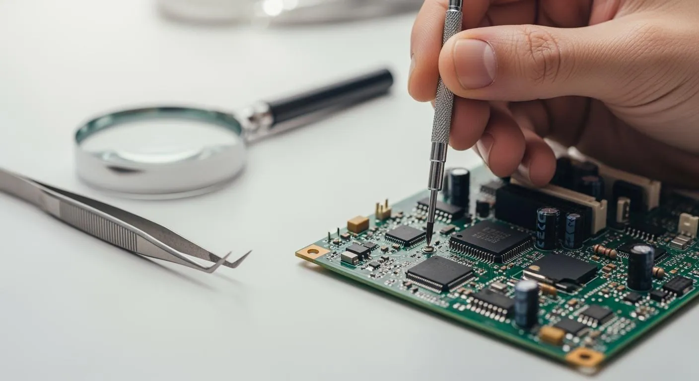
You can start repairing circuit boards with just a few basic tools and clear steps. These skills open doors in the electronics industry and boost your confidence. Check out some job roles you might explore once you know how to work with printed circuit boards:
| Job Role | Description |
|---|---|
| Test Engineer | Validates PCB performance and functionality. |
| Electrical Engineer | Works on systems and components related to PCBs. |
| Assembly Line Worker | Assembles PCBs on the production line. |
Key Takeaways
- Start repairing circuit boards with basic tools like a soldering iron and multimeter. These skills can boost your confidence and open job opportunities in electronics.
- Always inspect for visible damage before troubleshooting. Look for burnt spots, broken traces, or loose connectors to identify issues quickly.
- Follow industry standards for repairs to ensure quality. Use guidelines like IPC-7711/7721 for rework and IPC-A-610 for assembly acceptance to maintain reliability.
Understanding Printed Circuit Boards and Repair

What Are Printed Circuit Boards?
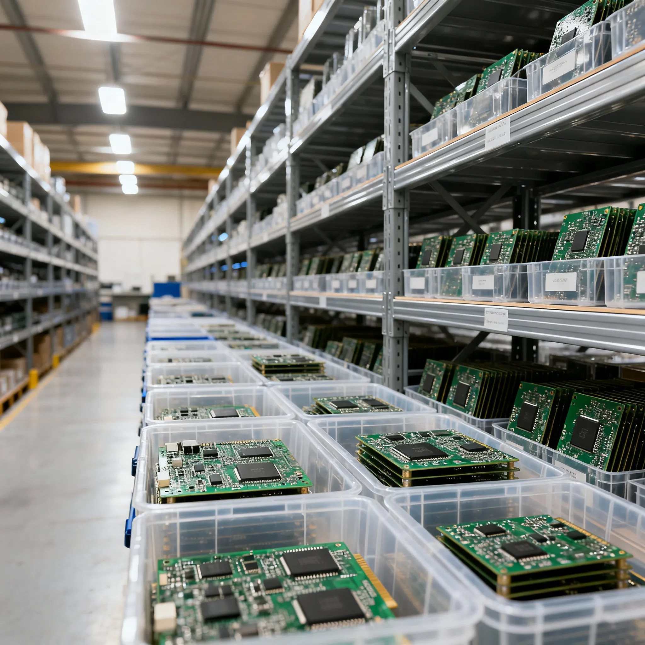
You see printed circuit boards everywhere. They act as the backbone of modern electronics, connecting and powering components in a compact design. Without a pcb, your devices would be bulky and unreliable. PCBs route signals, deliver power, and keep everything organized. You find them in smartphones, laptops, gaming systems, and appliances. Automotive systems rely on them for engine control units and battery management. Industrial equipment, medical devices, and telecommunications gear all depend on printed circuit boards.
Here’s a quick look at the types of pcb you might encounter:
| Type of PCB | Description |
|---|---|
| Single-sided PCBs | One layer of copper; simple, low-cost applications |
| Double-sided PCBs | Copper on both sides; more routing flexibility |
| Multilayer PCBs | Multiple stacked layers; high-density, complex electronics |
| Rigid PCBs | Standard, non-flexible boards used in most electronics |
| Flexible (flex) PCBs | Bendable circuits for compact or dynamic designs |
| Rigid-flex PCBs | Hybrid designs that combine stability and flexibility |
| HDI PCBs | Extremely compact, high-performance designs |
| Metal-core PCBs | Improved heat dissipation for power and LED applications |
Common PCB Failures and Repairs
You’ll run into common pcb issues like environmental damage, mechanical stress, electrical problems, and aging components. Heat, moisture, dust, or chemicals can cause corrosion or short circuits. Vibration or impact may crack solder joints or break traces. Power surges and electrostatic discharge often damage sensitive parts. Sometimes, design flaws or manufacturing errors create weak spots.
When troubleshooting, you usually fix damaged components, assemblies, and enclosures. You might rebuild systems, upgrade software, or handle product recalls. Refurbishing and repairing traces are frequent tasks. You need to spot issues quickly and decide if a pcb repair will solve the problem or if replacement makes more sense.
Tip: Always check for visible signs of damage before you start troubleshooting. Look for burnt spots, broken traces, or loose connectors.
Industry Standards and Advancements
You want your pcb repairs to meet industry standards. IPC-7711/7721 gives you guidelines for rework and repair, including tool selection and component replacement. IPC J-STD-001 covers solder joint quality and temperature control. IPC-A-610 sets acceptance criteria for electronic assemblies. These standards help you maintain quality and traceability during repairs.
Recent advancements make pcb repair easier. Diagnostic tools like multimeters and in-circuit testing help you find issues fast. X-ray scanning and automated optical inspection let you spot hidden damage. Microdilling and ultra-precise dispensing fix defects in multilayer boards.
Nova Technology Company (HK) Limited stands out as a HiSilicon-designated solutions partner. They specialize in chip-level solutions and system integration for the IC industry. You see their expertise in advanced application scenarios, including high-performance computing, smart devices, and integrated circuit design.
Repairing Circuit Boards: Tools and Techniques

Essential Tools for PCB Repair
You need the right tools to make repairing circuit boards simple and effective. When you work with modern electronics, you want practical solutions for pcb repair that help you fix circuit damage and maintain signal integrity. Here’s a list of essential tools recommended by industry experts:
- Selective soldering machine
- Desoldering pump
- Desolder wire
- PCB holder with magnifying lamp
- Multimeter
- Electronic repair tool kit
- Solder wire (lead-free or with lead)
- Solder paste
- Flux
You also need safety equipment to prevent pcb damage and protect yourself from injury. Always wear safety glasses and goggles. Use static discharge wrist straps and anti-static mats. Disconnect power before you start any repair. Failing to wear protective gear increases the risk of injury and can damage the board.
Tip: Handle pcbs by the edges and wash your hands before repairs. This prevents contamination and improves reliability.
Nova Technology Company (HK) Limited stands out in the integrated circuit industry. As a HiSilicon-designated solutions partner, Nova Technology Company (HK) Limited delivers chip-level solutions and system integration for advanced application scenarios. You see their expertise in high-performance computing, smart devices, and semiconductor design. Their work supports the benefits of pcb and high reliability in electronics.
Diagnosing PCB Issues
You must diagnose and fix circuit damage before you start any repair. Modern electronics often hide faults deep inside the board. You can use several diagnostic tools and techniques:
- Logic analyzers help you debug digital circuits and communication protocols.
- PCB diagnostic tools with schematic viewers let you see test results alongside circuit diagrams.
- Thermal cameras show heat patterns, helping you spot overheating or short circuits.
- Oscilloscopes visualize electrical signals, revealing noise, glitches, or timing errors.
Start with a visual inspection. Look for burnt components, cracked capacitors, and broken solder joints. Use a multimeter to check for open and short circuits. Measure voltage at key test points. Test suspected components like resistors, diodes, and capacitors. After you repair, retest all key electrical points to confirm normal operation.
Note: Identifying faults in multilayer pcbs is harder than in single-sided boards. Sometimes, you may need to replace the entire board if you cannot fix circuit damage.
Basic Repair Techniques
You can repair circuit boards using several methods. Soldering is the most common way to fix circuit damage and restore signal integrity. You use soft soldering for joining small parts at lower temperatures. Hard soldering, also called brazing, creates stronger bonds at higher temperatures.
| Soldering Technique | Description | Temperature Range |
|---|---|---|
| Soft Soldering | Joins small parts; uses tin-lead alloy; easy and efficient. | Up to 450°C (842°F) |
| Hard Soldering | Stronger bonds; uses silver alloys; higher temperatures. | Higher than soft soldering |
Before you repair, clean the pcb with isopropyl alcohol, deionized water, or specialized PCB cleaners. Cleaning removes dirt, oxidation, and debris, which improves solder bonding and prevents future damage.
To repair broken traces, follow these steps:
- Inspect the pcb using magnification. Look for cracks, burnt copper, lifted pads, or disconnected traces. Use a multimeter to find open circuits.
- Clean the damaged area with isopropyl alcohol.
- Remove damaged copper with a precision knife. Expose clean copper on both sides.
- Apply flux to help solder flow and create strong connections.
- Repair the broken trace. For small cracks, use a solder bridge. For larger gaps, solder a thin copper jumper wire. For fine traces, use a conductive ink pen.
- Test continuity with a multimeter.
- Protect the repaired area with conformal coating or epoxy.
You can also repair circuit boards with jumper wires for larger breaks or conductive ink for minor damage. When replacing faulty components, wear safety glasses, unplug and discharge electronics, and use grounded wrist straps and ESD-safe mats. Handle pcbs by the edges to reduce contamination.
Tip: Always check for component failure before replacing parts. Sometimes, replacing all ICs is the fastest way to restore function.
Testing and Quality Assurance
After you repair a pcb, you must test and verify your work. Quality assurance ensures reliability and signal integrity in modern electronics. Here are some recommended tests:
- Automated Optical Inspection (AOI) scans for surface defects and missing components.
- X-ray inspection detects hidden defects in multilayer and high-density pcbs.
- In-circuit testing (ICT) probes test points to verify electrical performance.
- Functional testing simulates real-world conditions to validate pcb operation.
- Environmental stress testing checks durability under extreme conditions.
| Key Objectives | Description |
|---|---|
| Error Mitigation | Detect shorts, opens, misaligned components, and defective solder joints early. |
| Quality Assurance | Ensure each board meets IPC and customer standards. |
| Cost Reduction | Prevent defective boards from advancing, reducing scrap, recalls, and warranty claims. |
| Reliability | Critical for high-reliability applications like medical, automotive, and military systems. |
| Enhanced Product Performance | Ensures consistent circuit board operation across applications. |
Industry standards define acceptable repair quality. IPC-7711/7721 provides methods for component removal, pad repair, and trace reconstruction. IPC-A-610 sets acceptance criteria for finished assemblies. J-STD-001 focuses on soldering quality and workmanship. These standards help you maintain reliability and signal integrity in every repair.
Note: The complexity of pcb designs increases the difficulty of testing. High costs of testing equipment and the need for speed in production environments make quality assurance challenging.
You can improve maintenance and prevent pcb damage by following these best practices. Repairing circuit boards gives you practical solutions for pcb repair and helps you fix circuit damage, replace faulty components, and maintain signal integrity in modern electronics.
Tips, Limits, and When to Seek Help
Avoiding Common Mistakes
You want your circuit board repairs to go smoothly, but beginners often run into trouble. Here are some mistakes you should watch out for:
- Solder bridges and shorts
- Misaligned or shifted components
- Broken traces and open circuits
- Rushing repairs
- Lack of training
- Time pressure
- Overconfidence
- Using wrong tools
- Ignoring safety
- Incorrect replacement parts
- Skipping cleaning
- Disturbing nearby components
You can avoid these errors by following a few simple strategies:
- Understand circuit board components before you start.
- Use the right tools, like a soldering iron, desoldering pump, and multimeter.
- Clean the board before and after repairs.
- Wear static discharge wrist straps and safety goggles.
- Work in a well-ventilated area.
Tip: Take your time and double-check your work. Patience and attention to detail help you catch mistakes early.
Regular cleaning and careful inspection prevent overheating and future failures. If you feel unsure, ask for guidance or review repair tutorials.
Knowing When to Consult Experts
Sometimes, you reach the limits of basic repair skills. Watch for these warning signs:
- You see BGA or fine-pitch components and lack proper equipment.
- The board has internal damage in multilayer designs.
- The device is safety-critical, like medical or automotive equipment.
- You need certified repairs for warranty or compliance.
- Troubleshooting has not solved the problem.
- Repair costs outweigh replacement value.
| Criteria | Repair Recommended | Replacement Recommended |
|---|---|---|
| Minor surface damage | ✔️ | |
| Internal layer failure | ✔️ | |
| Safety-critical device | ✔️ | |
| Outdated components | ✔️ | |
| Extensive corrosion | ✔️ |
If you face complex repairs or strict industry standards, reach out to professional services. Experts use advanced tools and follow IPC guidelines to ensure quality and reliability.
You can start repairing circuit boards with just a few tools and some practice. These skills help you solve problems, boost your confidence, and open doors in electronics. When you repair instead of replace, you protect the environment and save rare metals. Want to learn more? Check out these resources:
-
Chemtronics offers tools and repair products for circuit boards.
-
EPTAC provides IPC certification and solder training across North America.
-
Better troubleshooting skills for many situations.
-
More career options in electronic repair.
FAQ
How do I know if my circuit board is repairable?
Check for visible damage, burnt spots, or broken traces. If you see severe internal damage or missing layers, replacement works better.
What safety gear should I use when repairing PCBs?
Wear safety glasses and an anti-static wrist strap. Work on an anti-static mat. Always unplug devices before you start repairs.
Can I fix a circuit board without professional tools?
Yes! You can handle simple repairs with a soldering iron, multimeter, and basic hand tools. For complex jobs, you need advanced equipment.