Troubleshooting the 20151R: Common Pitfalls and How to Avoid Them in Your Circuit Design
Expert guide on Troubleshooting the 20151R: Common Pitfalls and How to Avoid Them in Your Circuit Design. Technical specs, applications, sourcing tips for engineers and buyers.
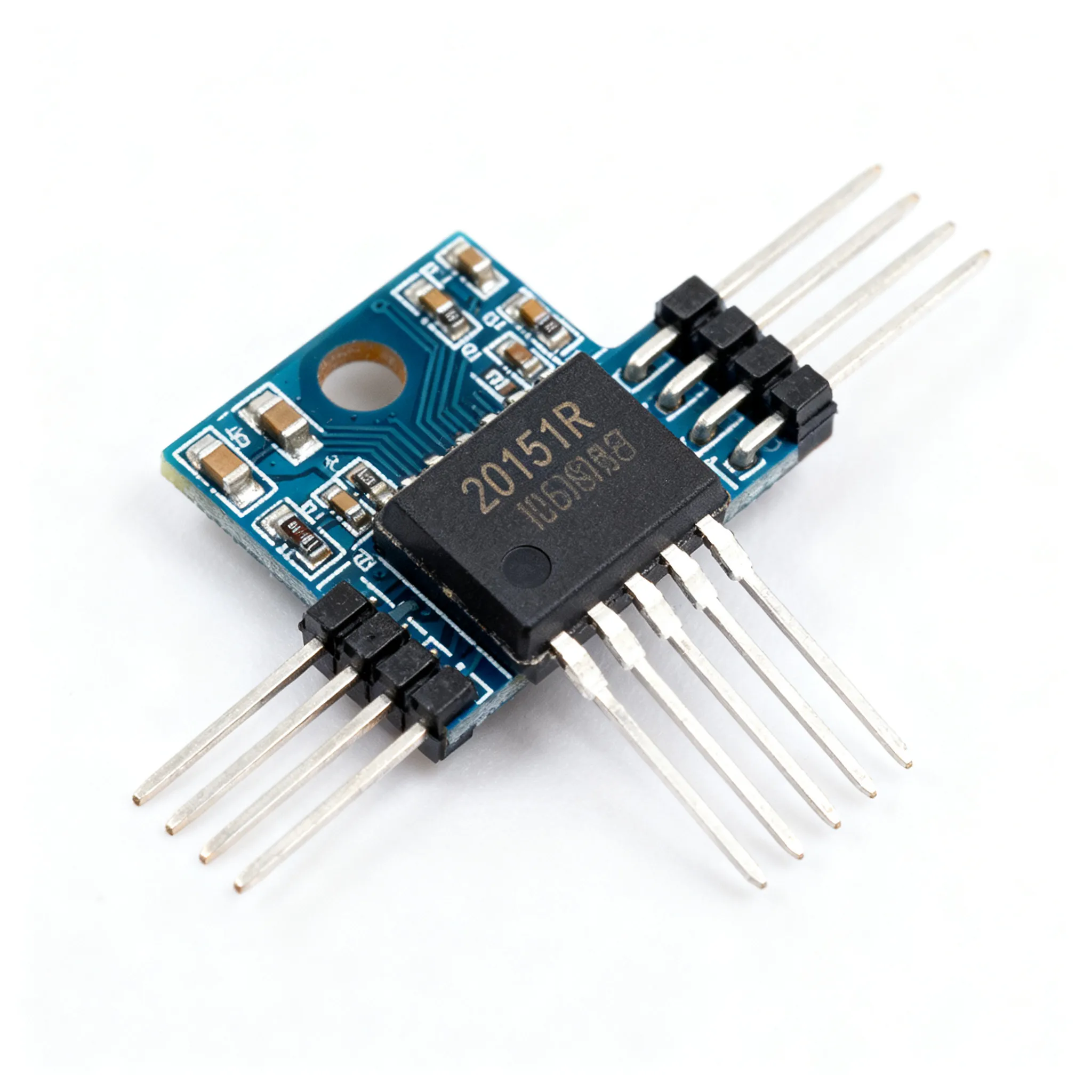
Troubleshooting the 20151R: Common Pitfalls and How to Avoid Them in Your Circuit Design
When a Tiny Resistor Network Grounds a Fleet: The Real Cost of 20151R Oversights
It’s easy to treat a resistor network like the 20151R as a commodity — a few cents’ worth of passives that pull up a bus and fade into the background. But when that network is the only thing holding an I²C line at a valid logic level, a marginal choice can cascade into intermittent data corruption, field returns, and even safety recalls. The automotive industry has just reminded us how a single component-level oversight can stop production lines and trigger massive recalls. In April 2025, a manufacturing defect in high-voltage battery cells caused internal short circuits, forcing OEMs to recall thousands of vehicles. Meanwhile, Stellantis recalled 65,348 Ram trucks over an instrument cluster software error that blanked the driver display. Both events share a common thread: a small, seemingly isolated failure propagated into a system-wide safety or usability crisis.
For engineers and procurement buyers, these headlines are not just news — they are a warning. A 20151R resistor network that drifts out of tolerance, cracks under thermal cycling, or is simply specified with the wrong pull-up value can produce exactly the kind of intermittent bus faults that lead to instrument cluster blackouts, sensor misreads, and ECU limp-home modes. Understanding the common pitfalls of integrating this part into your circuit design isn’t just good engineering practice; it’s a direct defense against the six common causes of PCB failure that OEMs know all too well — from solder joint fatigue to environmental contamination. When you’re designing a node that must survive 15 years of under-hood thermal shock, the 20151R deserves the same scrutiny as any active IC.
Decoding the 20151R: Resistance, Tolerance, and the Pull-Up Trade-Off
The 20151R is typically a 4-resistor isolated network in a compact SIP or SMD package, often deployed as pull-up resistors on I²C, SMBus, or other open-drain buses. Its job is deceptively simple: provide a known resistance between each data line and VDD so that the bus returns to a high logic level when no device is pulling it low. Yet the value of that resistance sets the entire electrical personality of the bus — rise time, noise margin, power consumption, and the maximum number of devices you can hang on the line.
Pull-up resistance directly controls how fast the bus capacitance charges. Too high a resistance, and the RC time constant stretches the rise time beyond the I²C specification, causing slave devices to miss clock edges or sample invalid data. Too low a resistance, and the bus wastes power, exceeds the sink current capability of the weakest driver, and may fail to pull the voltage down to a valid VOL. As the I²C pitfalls guide explains, incorrectly sized pull-up resistors lead to slow rise times that can cause slaves to miss clock edges entirely. The 20151R’s tolerance and temperature coefficient then add another layer of variability: a ±5% network at 25°C can become a ±7% network at 85°C if the TCR is poor, pushing an already marginal rise time over the edge.
Extracting these critical parameters from a datasheet is a skill in itself. The classic Troubleshooting Analog Circuits resource reminds us to look beyond the headline resistance and check the fine print: power rating per element, maximum working voltage, and the derating curve. For the 20151R, you’ll want to confirm that the network can handle the continuous current during a bus stuck-low fault without exceeding its rated temperature.
| I²C Mode | Max. Bus Speed | Typical Bus Capacitance | Recommended Pull-Up Range | Max. Rise Time (tr) | Key Constraint |
|---|---|---|---|---|---|
| Standard (Sm) | 100 kHz | ≤ 400 pF | 2.2 kΩ – 10 kΩ (4.7 kΩ typical) | 1000 ns | VOL ≤ 0.4 V at 3 mA sink |
| Fast (Fm) | 400 kHz | ≤ 400 pF | 1.5 kΩ – 3.3 kΩ (2.2 kΩ typical) | 300 ns | Rise time must meet 0.7×VDD threshold |
| Fast-mode Plus (Fm+) | 1 MHz | ≤ 550 pF | 470 Ω – 1.5 kΩ (1 kΩ typical) | 120 ns | Sink current up to 20 mA; check driver IOL |
| Ultra Fast (UFm) | 5 MHz | ≤ 100 pF | 100 Ω – 470 Ω | 50 ns | Unidirectional bus; push-pull drivers only |
These ranges are starting points. You must calculate the exact value based on your actual bus capacitance, which includes PCB traces, connector stubs, and the input capacitance of every device on the bus. A 20151R with a tight ±1% tolerance and a TCR of ±50 ppm/°C gives you the headroom to run closer to the upper resistance limit, saving power while staying within timing specs across the full temperature range. If your design must survive -40°C to +125°C, that TCR becomes non-negotiable.
Discrete Resistors vs. 20151R Networks: When Integration Beats Flexibility
Every design engineer faces the choice: place four individual 0402 or 0603 resistors, or drop in a single 20151R network. Both approaches can pull up an I²C bus, but the trade-offs ripple through layout, assembly, and test. Using a systematic troubleshooting framework like the one outlined in Cadence’s circuit troubleshooting techniques helps you evaluate these alternatives not just on paper, but in the context of real-world failure modes. Meanwhile, the FDA basic circuit analysis guide reinforces the importance of understanding parallel paths and parasitic elements that differ between discrete and integrated solutions.
| Comparison Metric | Discrete Resistors (4× 0402) | 20151R Resistor Network | Selection Criteria & Failure Boundary |
|---|---|---|---|
| Board Space | ~8 mm² (plus routing) | ~5 mm² (SIP/SOIC footprint) | Networks win on dense boards; discretes allow flexible placement near each IC. |
| Parasitic Capacitance | ~0.05 pF per resistor (negligible) | 0.5–2 pF between adjacent pins | At 1 MHz, network crosstalk can add jitter; discretes keep lines isolated. |
| Resistance Matching | ±1% to ±5% (unmatched) | ±0.5% to ±2% relative matching | Networks guarantee matched pull-ups, critical for differential or multi-drop buses. |
| Cost per Line (10k volume) | $0.003–$0.008 | $0.02–$0.05 | Discretes are cheaper per line, but assembly cost and placement time may offset. |
| Rework Complexity | Easy to swap one resistor | Must replace entire network | If one channel fails, a network forces a full replacement; discretes allow selective rework. |
| Thermal Tracking | Independent TCR drift | All resistors on common substrate track together | Networks maintain ratio stability over temperature; discretes may diverge. |
For most I²C pull-up applications, the 20151R network’s matching and space advantages outweigh the slightly higher component cost. However, if your bus has asymmetrical loading — one line sees 200 pF while another sees 50 pF — discrete resistors let you optimize each pull-up value independently. The network forces a one-size-fits-all resistance, which may compromise the worst-case line. When you’re troubleshooting a marginal bus, the ability to swap a single resistor can save hours of rework; with a network, you’ll need to lift the entire part, risking pad damage.
The Five Most Frequent 20151R Mistakes and How to Sidestep Them
Even seasoned engineers can fall into these traps. Each one has been observed in production designs and field returns, and each is entirely avoidable with a methodical approach. The electronic equipment troubleshooting guide stresses that one must understand the standard behind the circuit diagram before probing; the same principle applies to the 20151R — know the bus specification and the network’s datasheet limits before you commit to a value.
| Mistake | Symptom | Root Cause | Avoidance Strategy |
|---|---|---|---|
| 1. Wrong resistance for bus speed | Intermittent NACKs, data corruption at high temperature | Rise time exceeds spec; VIH not reached before ACK bit | Calculate RP(max) = tr / (0.8473 × Cbus). Validate with oscilloscope at all corners. |
| 2. Ignoring power dissipation during fault | Network discoloration, resistance drift, open circuit | Bus stuck low forces continuous current; P = VDD² / R exceeds package rating | Check power per element: Pmax = VDD² / R. Derate by 50% for ambient >70°C. Use higher resistance if possible. |
| 3. Neglecting derating at elevated temperatures | Resistance shift >5% at 105°C, timing failures | Power rating curve not consulted; self-heating adds to ambient | Apply derating curve from datasheet. For 125°C ambient, a 100 mW network may only handle 40 mW. |
| 4. In-circuit measurements that mislead | Multimeter reads 1.2 kΩ instead of 4.7 kΩ | Parallel paths through IC protection diodes or other pull-ups | Follow component testing best practices: lift one pin or remove network for accurate value. Use guarded measurements if in-circuit is unavoidable. |
| 5. Overlooking bus capacitance | Rise time too slow despite correct resistance | Trace length, connector stubs, and device input capacitance not summed | Estimate Cbus = Ctrace + Cpin × N + Cstub. Measure with a capacitance meter or TDR. Add series resistors on stubs to isolate capacitance. |
The fourth mistake — trusting an in-circuit resistance reading — is particularly insidious. As the PNP transistor testing guide wisely advises, “Remove from circuit for accuracy: In-circuit testing can be misleading due to parallel components.” The same holds for the 20151R. A bus with multiple devices often has ESD protection diodes that create sneak paths, making a 4.7 kΩ network measure as low as a few hundred ohms. If you must troubleshoot in-circuit, power down the board, discharge all capacitors, and use a multimeter with a low test voltage to avoid forward-biasing semiconductor junctions. Still, the only definitive test is to lift one common pin and measure each resistor individually.
The P2015 diagnostic trouble code case — where an intake manifold runner position sensor circuit falls out of range — serves as a powerful analogy. As described by Flagship One’s analysis, when the sensor signal goes out of range, the ECM defaults to a safe, limited fueling strategy, producing drivability symptoms. Similarly, when your 20151R’s pull-up resistance drifts out of the range that guarantees valid logic levels, the bus controller may not flag a hard fault — it simply starts missing ACKs, corrupting data, and forcing the system into a degraded mode that is maddeningly difficult to diagnose.
Your 20151R Questions Answered: From Selection to Troubleshooting
Q: How do I choose the right resistance value for my I²C bus speed when using a 20151R?
A: Start with the bus capacitance and required rise time. For Standard mode (100 kHz), 4.7 kΩ is typical; for Fast mode (400 kHz), 2.2 kΩ to 3.3 kΩ; for Fast-mode Plus (1 MHz), values as low as 1 kΩ may be needed. Always verify that the chosen value keeps VOL below 0.4 V and meets the sink current capability of the weakest device on the bus. Use the formula RP(min) = (VDD – VOL(max)) / IOL to set the lower bound, and RP(max) = tr / (0.8473 × Cbus) for the upper bound. The 20151R’s tolerance must keep you inside this window across temperature.
Q: Can I substitute a 20151R with a different tolerance network if the exact part is unavailable?
A: Yes, but evaluate the impact on bus timing. A tighter tolerance (e.g., ±1% vs. ±5%) improves consistency across production, while a looser tolerance may cause marginal rise times at temperature extremes. For non-critical, low-speed buses, a ±5% network may suffice; for high-speed or noise-sensitive designs, stick to ±1% or better. If you must substitute, recalculate the worst-case resistance at the tolerance extremes and verify that rise time and VOL still meet the I²C spec. Also check the TCR — a ±5% network with a poor TCR can drift well beyond ±5% at -40°C or +125°C.
Q: What is the best way to test a 20151R in-circuit without desoldering?
A: In-circuit resistance measurements are often misleading due to parallel paths. If you must test in-circuit, power down the board, discharge all capacitors, and use a guarded multimeter with a low test voltage (e.g., 0.2 V) to avoid turning on semiconductor junctions. For accurate value verification, lift one pin or remove the network entirely, as recommended in component testing guides. A safer in-circuit technique is to measure the bus rise time with an oscilloscope and back-calculate the effective pull-up resistance using the RC time constant, but this assumes you know the exact bus capacitance.
Q: How does temperature affect the 20151R’s performance in automotive environments?
A: The 20151R’s temperature coefficient of resistance (TCR) dictates drift. In under-hood applications with wide temperature swings, a network with ±100 ppm/°C TCR can shift resistance by several percent, altering rise times. For example, a 4.7 kΩ resistor with ±100 ppm/°C can change by ±0.47 Ω/°C; over a 165°C span (-40°C to +125°C), that’s up to 77.5 Ω, or 1.65%. While this seems small, it can be enough to push a marginal rise time over the limit. Select a low-TCR variant (e.g., ±50 ppm/°C) and derate power dissipation to keep self-heating minimal. The Troubleshooting Analog Circuits resource emphasizes checking the derating curve: a 100 mW network at 70°C may only handle 60 mW at 125°C.
Q: What are the lead-time risks for the 20151R, and how can procurement mitigate them?
A: Resistor networks can face allocation during supply crunches, especially in niche packages. Mitigate by qualifying a second-source network with identical footprint and electrical specs, maintaining safety stock based on forecast, and working with distributors to secure buffer inventory. Early design-in of alternate part numbers prevents line-down situations. For mixed BOM flexibility, platforms like IC-Online allow you to source multiple manufacturer equivalents and negotiate flexible MOQs, reducing single-source dependency.
Q: What failure modes should I look for when a 20151R causes intermittent bus errors?
A: Look for cracked solder joints due to thermal cycling, moisture ingress causing dendritic growth, or internal opens from mechanical stress. Intermittent errors often appear as occasional NACKs or data corruption. Use freeze spray and a thermal camera to isolate temperature-sensitive faults, and inspect under magnification for hairline fractures. A network that measures correctly at room temperature but opens at 85°C is a classic sign of a latent manufacturing defect. If the bus works reliably with a different pull-up network, you’ve found your culprit.
References & Further Reading
- 6 Common Causes of PCB Failure: What OEMs Should Know – Matric Group
- Recalls You Need to Know About in April 2025 – Work Truck Online
- Car Recall Guide: Steps to Handle a Safety Notice – Consumer Reports
- Ram Recalls 65,348 Trucks Over Instrument Cluster Failure – MoparInsiders
- Circuit Troubleshooting Techniques: A Practical Guide – Cadence
- P2015 Code Symptoms, Causes, Diagnosis & Repair Procedures Guide – Flagship One
- FDA, Inc. Basic Circuit Analysis and Trouble Shooting – DiscountPDH
- Demystifying I2C: Common Pitfalls and How to Avoid Them – Akshat Nerella, Medium
- Troubleshooting Electronic Equipment Guide – Scribd
- Troubleshooting Analog Circuits – changpuak.ch
- How to Test a PNP Transistor with a Digital Multimeter – Nevsemi Electronics
- IC-Online – Electronic Components Sourcing
The 20151R may be a passive component, but its impact on bus reliability is anything but passive. By treating resistance selection as a design calculation rather than a rule of thumb, verifying tolerance and TCR against your operating environment, and adopting disciplined in-circuit troubleshooting habits, you can eliminate the root cause of many intermittent communication failures. When procurement and engineering align early on second sources and buffer stock, the 20151R becomes a solved problem rather than a last-minute fire drill. For mixed BOM sourcing and flexible MOQ options that keep your production lines moving, visit IC-Online to explore a wide range of resistor networks and alternative part numbers.