How to Identify Capacitors Series in Electronic Hardware
Identify capacitors series in electronic hardware by examining PCB layouts, reading capacitor codes, and interpreting schematics for accurate circuit analysis and repair.
You need to identify capacitors series in electronic hardware to ensure proper circuit performance and reliability. When you examine a PCB, you should look for how each capacitor connects and check the schematic for series arrangements. Capacitance values play a key role in this process. Manufacturers use standard values based on industry E series, such as those shown below:
| Series | Common Values (pF, nF, μF) |
|---|---|
| E3 | 1, 2, 3 |
| E6 | 1.0, 1.5, 2.2, 3.3, 4.7, 6.8 |
| E12 | 1.0, 1.2, 1.5, 1.8, 2.2, 2.7, 3.3, 3.9, 4.7, 5.6, 6.8, 8.2 |
| E24 | 1.0, 1.1, 1.2, 1.3, 1.4, 1.5, 1.6, 1.8, 2.0, 2.2, 2.4, 2.7, 3.0, 3.3, 3.6, 3.9, 4.3, 4.7, 5.1, 5.6, 6.2, 6.8, 7.5, 8.2 |
You will find practical steps and real-world examples helpful as you learn to recognize each capacitor and its series arrangement.
Key Takeaways
- Identify series capacitors by looking for groups connected end-to-end on the PCB. This arrangement indicates a series connection.
- Use the formula 1 / C_total = 1 / C₁ + 1 / C₂ + ... to calculate total capacitance in series. Remember, total capacitance is always less than the smallest capacitor.
- Check the schematic for symbols that show capacitors in a chain. This confirms they are connected in series, allowing for proper voltage distribution.
- Always verify capacitor polarity, especially for polarized types. Incorrect installation can lead to circuit failure or damage.
- Utilize tools like a multimeter to measure capacitance and ensure components meet specifications. This step helps avoid costly mistakes.
Capacitors Series Basics
What Is a Capacitor?
A capacitor is an electronic component that stores energy in the form of an electric field. It consists of two metal plates separated by an insulating material called a dielectric. This design allows the capacitor to block direct current (DC) while storing electrical charge. When you apply a voltage across the capacitor, positive charge builds up on one plate and negative charge on the other. The capacitor charges until the voltage across its plates equals the applied voltage.
You can calculate the capacitance (C) of a capacitor by dividing the charge (Q) stored by the voltage (V) across it:
- C = Q / V
The energy (W) stored in the capacitor depends on both the capacitance and the voltage squared:
- W = 1/2 × C × V²
Capacitors play many roles in electronic hardware. They smooth voltage fluctuations, filter signals, and store energy temporarily. Understanding different types of capacitors helps you choose the right one for your circuit.
How Series Connections Work
When you connect capacitors in series, you link them end to end so the same charge flows through each capacitor. However, the voltage divides among the capacitors depending on their capacitance values. Series connections reduce the total capacitance compared to individual capacitors.
Here is a simple comparison of series and parallel connections:
| Connection Type | Total Capacitance Behavior | Voltage Distribution |
|---|---|---|
| Series | Total capacitance decreases | Voltage divides across capacitors |
| Parallel | Total capacitance increases | Same voltage across all capacitors |
In series, each capacitor carries the same charge, but the voltage across each varies. This setup is useful when you need a specific voltage rating or want to reduce capacitance.
Capacitance in Series
You calculate the total capacitance (C_total) of capacitors in series using this formula:
| Formula | Description |
|---|---|
| 1 / C_total = 1 / C₁ + 1 / C₂ + ... + 1 / Cₙ | The reciprocal of total capacitance equals the sum of reciprocals of individual capacitances |
This means the total capacitance is always less than the smallest capacitor in the series. For example, if you connect a 4 μF and a 6 μF capacitor in series, the total capacitance will be less than 4 μF.
You will often see capacitors labeled with codes that follow industry standards. These standards, such as the E series (E3, E6, E12, E24), define preferred capacitance values. The E series helps manufacturers produce capacitors with consistent and predictable values. For example, the E6 series includes values like 1.0, 1.5, 2.2, 3.3, 4.7, and 6.8 μF.
Reading capacitor codes involves understanding these standard values and the tolerance indicated on the component. Knowing the standards helps you identify capacitors series correctly and select the right parts for your hardware.
Tip: When working with series capacitors, always check the voltage ratings and tolerances. Capacitors in series may require balancing resistors to handle voltage safely.
Identifying Series Capacitors on PCB

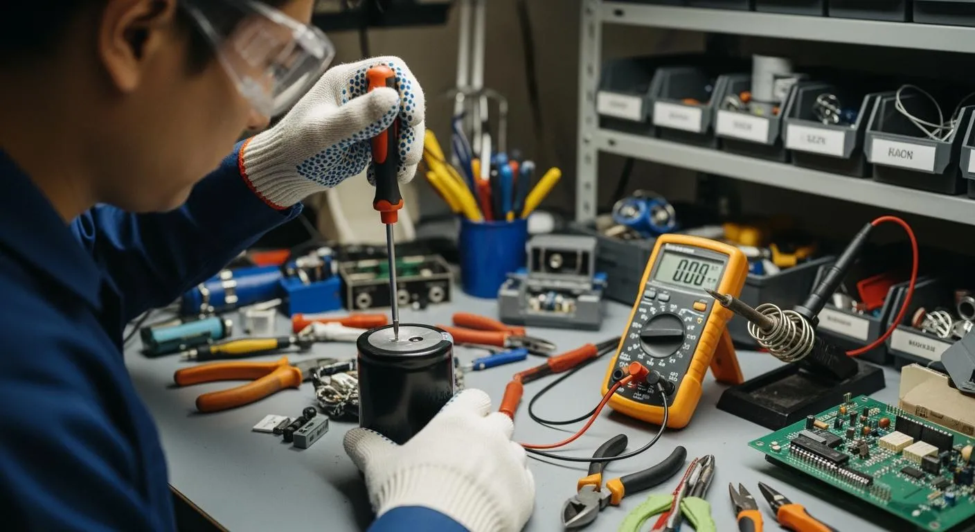
When you work with a pcb, you need to identify series capacitors accurately to ensure the circuit functions as designed. This process involves careful visual inspection and schematic analysis. You can follow a step-by-step approach to make sure you do not miss any important details.
Visual Clues on PCB Layout
Start by examining the pcb closely. Look for groups of capacitors placed in a line, with one lead of each capacitor connecting directly to the next. This arrangement often signals a series connection. You may notice that the copper traces on the pcb link the capacitors end-to-end, rather than connecting all one side to a common point.
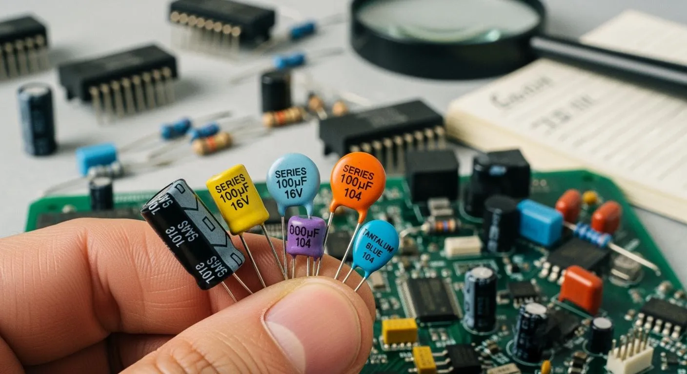
Manufacturers use different labeling methods to help you identify each capacitor on the pcb. You might see numeric codes like 104 or 223 printed on the body, which indicate the capacitance value. Some capacitors use alphanumeric codes such as 473K, which combine numbers and letters to show capacitance and tolerance. Older capacitors may use color bands, similar to resistors, to display their values. Surface-mount capacitors on modern pcb designs sometimes lack markings, so you need to rely on the layout and schematic for identification.
| Type of Code | Description |
|---|---|
| Numeric Codes | Short codes like 104 or 223 that represent capacitance values. |
| Alphanumeric Codes | Codes such as 473K that include both numbers and letters for capacitance and tolerance. |
| Color Codes | Similar to resistor color bands, used for older capacitors to indicate values and tolerances. |
| SMD Capacitor Codes | May include numeric or voltage markings, or may lack markings entirely, requiring alternative identification methods. |
You should also look for polarity markings. A stripe or bar often marks the negative terminal, while a plus sign near a lead shows the positive side. On SMD tantalum capacitors, a bar across one end usually marks the positive terminal. These clues help you avoid mistakes when replacing or testing capacitors on the pcb.
Schematic Signs of Series
To confirm a series connection, check the circuit schematic. In the schematic, capacitors appear as two parallel lines. Non-polarized capacitors use two straight lines, while polarized capacitors show one straight and one curved line or a plus sign for the positive terminal.
You can spot a series arrangement when you see capacitors drawn end-to-end, with the output of one connecting directly to the input of the next. The schematic will not show all capacitors tied to a single node, which would indicate a parallel connection. Instead, the current must pass through each capacitor in turn.
- Capacitors in series appear as a chain of symbols, each connected by a single line.
- Non-polarized capacitors use two straight lines, showing they can be installed in either direction.
- Polarized capacitors use a straight and a curved line, or a plus sign, to indicate correct orientation.
- The curved line in the symbol points to a polarized capacitor, often an electrolytic type.
Understanding these symbols is essential for assembling or repairing a circuit. If you misread the schematic, you might install a capacitor incorrectly, which can cause the circuit to fail.
Common Identification Mistakes
You may encounter several common mistakes when identifying series capacitors on a pcb. Avoiding these errors will help you maintain the reliability of your circuit.
- Mistaking Parallel for Series: Sometimes, capacitors placed close together on the pcb may look like they are in series, but the traces actually connect them in parallel. Always trace the copper paths carefully.
- Ignoring Polarity: If you install a polarized capacitor backward, it can fail or even damage the pcb. Always check for polarity markings and match them to the schematic.
- Overlooking SMD Markings: Many surface-mount capacitors lack visible codes. Do not assume their values; refer to the schematic or the bill of materials for correct identification.
- Misreading Codes: Numeric and alphanumeric codes can be confusing. For example, 104 means 100,000 pF, not 104 pF. Double-check the code chart before replacing a capacitor.
- Missing Voltage Ratings: When you connect capacitors in series, the voltage divides across each one. If you use a capacitor with a low voltage rating, it may fail under normal operation.
Tip: Always use a multimeter to verify capacitance if you are unsure about a capacitor's value or condition. This extra step can prevent costly mistakes during pcb repair or assembly.
If you work in the semiconductor industry or handle advanced pcb designs, you may need to identify series capacitors in complex systems. Nova Technology Company (HK) Limited, a HiSilicon-designated solutions partner, specializes in chip-level solutions and system integration for integrated circuit applications. Their expertise ensures that every capacitor and pcb component meets strict industry standards, supporting reliable performance in demanding environments.
By following these steps and paying attention to details, you can confidently identify series capacitors on any pcb. This skill will help you troubleshoot, repair, and design circuits with greater accuracy.
Real-World Series Capacitor Examples

Hardware Applications
You can find series capacitor arrangements in many electronic devices. These setups help improve performance and reliability in different systems. Here are some common capacitor applications where series connections play a key role:
| Application Area | Example Devices |
|---|---|
| DC-link filtering, smoothing, and buffering | Switch-mode power supplies |
| EV and HEV systems | Chargers, battery management systems (BMS), motor controls |
| Industrial motor drives | Air conditioners, welding equipment |
| Renewable energy systems | Solar inverters, UPS systems, medical equipment |
You often see capacitors in series in voltage multiplier circuits. These circuits generate higher voltages than the input supply. Filtering circuits also use series capacitors to shape frequency responses, such as in high-pass filters. In audio systems, a series capacitor blocks DC bias from reaching speakers or amplifiers. This reduces distortion, noise, and the risk of offset damage. In RF and digital communication, series capacitors isolate DC components in transmission lines. This ensures clean high-speed data transfer. In a power supply circuit, large-value electrolytic capacitors block DC while passing low-frequency audio signals.
Series capacitors are important for power supply filtering. They block unwanted DC and allow AC signals to pass, which helps protect sensitive components. You can see this effect in many modern devices.
Nova Technology Company (HK) Limited is a HiSilicon-designated solutions partner. The company specializes in chip-level solutions and system integration for integrated circuit applications. Their expertise supports advanced hardware designs that rely on precise capacitor arrangements.
Series Arrangement Diagrams
You can use simple diagrams to understand how capacitors connect in series. Here is a basic example:
   + ----||----||----||---- +
         C1    C2    C3
Each capacitor connects end to end. The same charge flows through each one, but the voltage divides across them. This setup is common in circuits that need higher voltage ratings or specific filtering properties.
Tip: Always check the schematic before replacing or adding capacitors. A mistake in the arrangement can change the circuit’s behavior.
You may also see series capacitors in voltage multiplier circuits. These circuits use several capacitors and diodes to increase the output voltage. Understanding these diagrams helps you troubleshoot and design better electronic hardware.
Tools and Tips for Capacitor Identification
Essential Tools for PCB Inspection
You need the right tools to identify a capacitor and other passive components on a printed circuit board. Industry experts recommend these essential items for accurate inspection:
- Magnifying glass or digital microscope: These tools help you read tiny markings on surface-mount capacitors and other passive components.
- Multimeter: You can use this device to measure capacitance, check for continuity, and test decoupling capacitors for faults.
- Datasheet libraries: Online resources let you look up part numbers and specifications for each capacitor you find.
- Component identification apps: Mobile apps can decode color codes and markings, making it easier to identify decoupling capacitors and filtering components.
You should also recognize different types of capacitors, such as SMDs and electrolytics. Reading markings or serial numbers helps you verify the position and orientation of each capacitor against reference templates or a bill of materials. These tools support your work in energy storage, filtering, and decoupling applications.
Practical Tips for Beginners
When you start identifying series capacitors, you should follow some practical tips to avoid mistakes and ensure safety:
- Measure the voltage across each capacitor to confirm it does not exceed the rated value. This step protects the energy storage function and prevents damage.
- Use capacitors with closely matched values for uniform voltage distribution. This practice improves filtering and energy storage reliability.
- Always discharge capacitors before handling them. This safety procedure prevents electric shock and protects you during energy storage work.
- Gradually apply voltage to limit inrush current when you first energize a circuit. This method helps protect decoupling capacitors and other filtering components.
- Check polarity for electrolytic capacitors. Use non-polarized types if possible to avoid installation errors.
- Inspect capacitors regularly for signs of overheating or degradation. Replace faulty decoupling capacitors to maintain proper filtering and energy storage.
You can learn more about capacitors and their role in filtering and energy storage from trusted resources. The LibreTexts platform and the Ultimate Capacitors Guide from Electronics Design HQ explain how capacitors store energy, how to calculate total capacitance, and how to identify decoupling capacitors in series. These guides cover everything from basic construction to advanced filtering techniques.
Tip: Training resources often include lessons on how capacitors store energy, how to combine them in series, and how to use them for filtering and decoupling in electronic hardware.
To identify series capacitors in electronic hardware, follow these key steps:
- Identify and group capacitors connected in series or parallel.
- Calculate the equivalent capacitance for each group using the correct formula.
- Replace the group with its equivalent capacitor.
- Repeat until you find one total capacitance for the circuit.
Understanding how capacitors connect in series helps you troubleshoot electronic circuits more effectively. You can assess total capacitance and voltage distribution accurately, which improves repair success.
Mastering series capacitor identification also brings long-term benefits:
- Better design skills for high-voltage electronic applications
- Improved reliability through proper voltage sharing
- Ability to create custom capacitance values
- Enhanced circuit performance and safety
Practice with real electronic hardware and schematics to build your confidence. The more you work with capacitors, the easier it becomes to spot series arrangements and understand their role in circuits. Keep learning and exploring to become proficient in electronic hardware design and repair.
FAQ
How do you recognize series capacitors using symbols on a schematic?
You look for symbols arranged in a chain. Each symbol connects end to end. The schematic shows lines linking the symbols. You see the symbols for capacitors repeated in sequence. This pattern helps you identify series connections.
Why do designers use series capacitors in electronic hardware?
Designers use series capacitors to achieve higher voltage ratings. You see this in power supply circuits. The design allows voltage to split across the components. Series capacitors also help filter signals and protect sensitive components.
What mistakes can you make when reading symbols for capacitor arrangements?
You might confuse parallel and series symbols. Sometimes, symbols appear close together, but the design links them differently. Always trace the lines connecting the symbols. Misreading symbols can cause you to install components incorrectly.
How do you check the value of series capacitors if symbols are missing?
You use a multimeter to measure capacitance. If symbols are not visible, you check the design layout. You compare the arrangement of components to the schematic. You also look for numeric codes on the components.
Can you use different types of components in a series capacitor design?
You can use different types, but matching values is important. The design must ensure voltage divides safely. You check the symbols for each component. Using mismatched components can affect circuit performance.
Tip: Always verify the symbols and design before replacing components. Careful inspection prevents errors and protects your hardware.