3 Input NAND Gate Truth Table Explained for Beginners
You see the 3 input nand gate truth table answers a key question in digital logic. This gate gives a LOW (0) output only whe

You see the 3 input nand gate truth table answers a key question in digital logic. This gate gives a LOW (0) output only when all three inputs are HIGH (1). In every other case, the output stays HIGH. The Boolean expression for this gate is Y = ¬(A · B · C). You can use NAND gates to build any other logic gate, making them universal in electronics.
Key Takeaways
- A 3-input NAND gate outputs LOW only when all three inputs are HIGH; otherwise, it outputs HIGH.
- You can build any logic gate using only NAND gates, making them universal and very useful in digital circuits.
- The Boolean expression for the 3-input NAND gate is Y = NOT (A AND B AND C), which helps simplify circuit design.
- You can create a 3-input NAND gate by combining multiple 2-input NAND gates, but ready-made ICs like the 74HC10 make this easier.
- 3-input NAND gates are common in many devices, helping control actions that depend on multiple conditions being true.
3 Input NAND Gate Truth Table
Inputs and Outputs
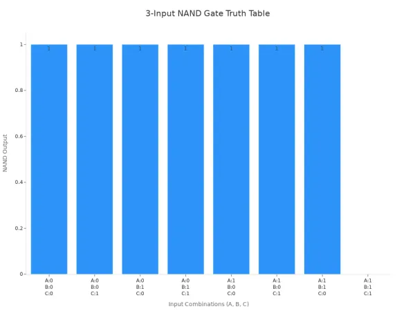
When you look at the 3 input nand gate truth table, you see all possible combinations of three digital inputs: A, B, and C. Each input can be either 0 (LOW) or 1 (HIGH). The output depends on these inputs. The table below shows every possible combination and the output for each:
| A | B | C | Output |
|---|---|---|---|
| 0 | 0 | 0 | 1 |
| 0 | 0 | 1 | 1 |
| 0 | 1 | 0 | 1 |
| 0 | 1 | 1 | 1 |
| 1 | 0 | 0 | 1 |
| 1 | 0 | 1 | 1 |
| 1 | 1 | 0 | 1 |
| 1 | 1 | 1 | 0 |
You notice that the output is 1 (HIGH) for every row except the last one. Only when all three inputs are 1 does the output become 0 (LOW). This is the key rule for the 3 input nand gate truth table. You can use this table to predict how the gate will behave in any digital circuit.
Tip: The 3 input nand gate truth table helps you design circuits that need a specific output only when all conditions are met.
Boolean Expression
The behavior of the 3-input NAND gate follows a simple Boolean expression. You write it as:
Y = ¬(A · B · C)
This means the output Y is the NOT (inverted) result of the AND operation between A, B, and C. If you AND all three inputs and then invert the result, you get the output of the NAND gate. In digital logic, this is very important because it lets you build more complex circuits using just NAND gates.
The symbol for a 3-input NAND gate looks like an AND gate with three input lines and a small circle (called a "bubble") at the output. This bubble shows that the output is inverted. In some diagrams, you might see a rectangular symbol with an "&" inside and a bubble at the output. Both symbols mean the same thing.
- The NAND gate outputs LOW only when all three inputs are HIGH.
- You can use the Boolean expression to simplify and analyze digital circuits.
- NAND gates are universal, so you can create any other logic gate using only NAND gates.
Note: Understanding the Boolean expression and the gate symbol helps you read and draw circuit diagrams more easily.
Operation

Logic Rule
You can understand the 3-input NAND gate by looking at its logic rule. The gate checks three inputs: A, B, and C. If all three inputs are HIGH, the output turns LOW. In every other case, the output stays HIGH. This matches the rule found in datasheets for chips like the 74LS10 and 7412. The output follows the formula:
X = NOT (A AND B AND C)
This means the gate works as a negated AND function. You see this behavior in digital circuits when you want the output to be LOW only if every input is HIGH. This rule helps you design circuits that react only when all conditions are true.
Tip: If you remember that a NAND gate always inverts the AND result, you can predict its output for any input combination.
Gate Construction
You can build a 3-input NAND gate using only 2-input NAND gates. Here is a simple way to do it:
- Connect inputs A and B to the first 2-input NAND gate. This gives you ¬(A·B).
- Use a second 2-input NAND gate as an inverter. Tie both inputs of this gate to the output from step 1. Now you have (A·B).
- Connect the output from step 2 and input C to a third 2-input NAND gate. This gives you ¬((A·B)·C), which matches the 3-input NAND gate output.
- You need three 2-input NAND gates for this setup.
- If you care about timing, remember that the path with A and B has more delay than the path with C. You can add an inverter to the C input to balance the delay.
Using only 2-input NAND gates increases the number of gates and makes the circuit more complex. Simulation tools like Logisim use this method to create multi-input gates.
You can also use ready-made ICs for 3-input NAND gates. The 74HC10 and 74LS10 chips are popular choices. These chips contain three separate 3-input NAND gates in one package. Here is a quick look at their features:
| Feature | Description |
|---|---|
| Functionality | Three independent 3-input NAND gates |
| Pin Count | 14 pins |
| Power Supply | +5V (VCC) and Ground (GND) |
| Pin Configuration | Inputs and outputs for three separate NAND gates |
| Equivalents | 74HC10, 74HCT10, 74LS10, 74LVC10, 74AC10, 74ALS10 |
| Alternatives | 74×12 (open-collector outputs), CD4023 |
You can find these ICs in many digital projects. They make it easy to add 3-input NAND gates without building them from scratch. Manufacturers also provide details like supply voltage, output current, and noise immunity in datasheets. This helps you choose the right chip for your circuit.
Truth Table Breakdown
All LOW Inputs
When you set all three inputs of a NAND gate to LOW (0), you get a HIGH (1) output. This result comes directly from the 3 input nand gate truth table. You can see this in the table below:
| Input A | Input B | Input C | Output Q |
|---|---|---|---|
| 0 | 0 | 0 | 1 |
If you look at the chart, you notice that the output stays HIGH when all inputs are LOW.

You can use this behavior to make sure your circuit starts with a HIGH output when no signals are present.
Mixed Inputs
You often see circuits where the inputs are a mix of HIGH and LOW values. In these cases, the output of the NAND gate remains HIGH. The gate only switches to LOW when every input is HIGH. If you set any input to LOW, the output stays HIGH no matter what the other inputs do. This rule helps you design circuits that ignore certain conditions unless all signals are present.
- If you set A = 1, B = 0, C = 1, the output is HIGH.
- If you set A = 0, B = 1, C = 1, the output is HIGH.
This pattern repeats for every combination except when all inputs are HIGH. You can use the 3 input nand gate truth table to check each case. When troubleshooting, you should remember that if one input is LOW, the output will always be HIGH. This makes it easier to find problems in your circuit.
Engineers use this rule to simplify analysis. If you see a LOW input, you know the output will be HIGH, so you can focus on other parts of the circuit.
All HIGH Inputs
When you set all three inputs to HIGH (1), the NAND gate gives a LOW (0) output. This is the only case where the output changes from HIGH to LOW. You can use this feature to trigger actions only when every condition is met. For example, you might want a warning light to turn on only when three sensors detect a problem at the same time.
| Input A | Input B | Input C | Output Q |
|---|---|---|---|
| 1 | 1 | 1 | 0 |
You can use the truth table to confirm this result. If you see a LOW output, you know all inputs are HIGH. This helps you check for stuck inputs or wiring problems. The truth table also helps you understand "don't care" inputs. If one input is LOW, you do not need to check the others because the output will be HIGH.
The truth table gives you a clear map for troubleshooting. You can quickly find errors and make sure your circuit works as expected.
Importance
Universal Gate
You need to understand the 3 input nand gate truth table because it forms the foundation of digital electronics. The NAND gate is called a universal gate. This means you can use it to build any other logic gate, such as AND, OR, or NOT. You only need NAND gates to create complex digital circuits.
NAND gates have a special property. They are functionally complete. This means you can connect them in different ways to make any logic function. For example, you can make a NOT gate by connecting both inputs of a NAND gate to the same signal. You can build an AND gate by using two NAND gates together. You can even create an OR gate by combining NAND gates and using a rule called De Morgan’s theorem.
When you use only NAND gates, you make your circuit design simpler. You need fewer types of chips, which makes your project easier to build and fix.
Here are some reasons why the universal property of NAND gates is important:
- You can design any digital system using only NAND gates.
- You reduce the number of different parts you need.
- You can make your circuits smaller and faster.
- You save power and space, especially in large projects.
Applications
You will find 3-input NAND gates in many digital devices. These gates help you create both simple and complex logic circuits. Here are some common uses:
- You can use NAND gates to make inverters, AND gates, and OR gates.
- You can build combinational logic circuits, which make decisions based on several inputs.
- You can create sequential circuits, like latches and flip-flops, which store information.
- NAND gates are used in flash memory, where they help store data safely.
- Integrated circuits use NAND gates to perform logic functions in a small space.
- Home security systems use NAND gates to check if all sensors are triggered before sounding an alarm.
- IoT devices, like automatic watering systems, use NAND gates to control actions based on sensor signals.
Here is a table that shows some advantages of using 3-input NAND gates compared to other gates:
| Advantage Aspect | 3-input NAND Gates | Other Logic Gates (AND/OR) |
|---|---|---|
| Transistor Count | Fewer (4) | More (6) |
| Power Consumption | Lower | Higher |
| Circuit Size | Smaller | Larger |
| Flexibility | Can create any logic gate | Less flexible |
| Speed (TTL) | Faster | Slower |
You can see that using NAND gates helps you build efficient, reliable, and flexible digital systems. By learning the 3 input nand gate truth table, you gain the skills to design and understand many types of electronic circuits.
You learned that the 3-input NAND gate outputs HIGH for every input combination except when all inputs are HIGH. The truth table below helps you remember this for exams:
| Inputs (A, B, C) | Output (Y) |
|---|---|
| 0, 0, 0 | 1 |
| 0, 0, 1 | 1 |
| 0, 1, 0 | 1 |
| 0, 1, 1 | 1 |
| 1, 0, 0 | 1 |
| 1, 0, 1 | 1 |
| 1, 1, 0 | 1 |
| 1, 1, 1 | 0 |
Mastering truth tables gives you a clear way to check circuit logic and helps you design reliable systems. You can start with breadboard projects using TTL chips or build gates with transistors. As you practice, you discover how NAND gates let you create all basic logic functions, preparing you for advanced digital design.
FAQ
What does a 3-input NAND gate do?
A 3-input NAND gate checks three signals. If all three are HIGH, you get a LOW output. For any other combination, the output stays HIGH. This makes it useful for circuits that need a specific condition to trigger.
Can I build other gates using only NAND gates?
Yes! You can create any logic gate using just NAND gates. For example, connect both inputs of a NAND gate together to make a NOT gate. Combine several NAND gates to build AND, OR, and more.
Why is the output HIGH when not all inputs are HIGH?
The NAND gate inverts the result of the AND operation. If any input is LOW, the AND result is LOW, so the NAND output becomes HIGH. Only when all inputs are HIGH does the output turn LOW.
Where do you use 3-input NAND gates in real life?
You find 3-input NAND gates in alarm systems, digital locks, and control panels. They help check if several conditions happen at the same time before taking action.
What is the Boolean expression for a 3-input NAND gate?
You write the Boolean expression as:
Y = ¬(A · B · C)
This means the output Y is the NOT of the AND of A, B, and C.