Decoding the Microfarads Symbol for Circuit Enthusiasts
The microfarads symbol (μF, uF, MFD) shows a capacitor’s value in circuits. Learn how to read and use the microfarads symbol in daily electronics.
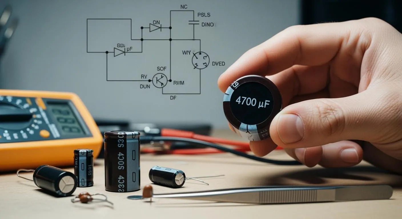
You often see the microfarads symbol as μF, uF, or MFD on capacitors, multimeters, and electronic schematics. This symbol tells you a component’s capacitance, which helps you choose the right part for your project. Recognizing these markings lets you identify and use capacitors correctly. Try searching for these symbols on your own devices and circuit boards—they are everywhere in electronics.
Key Takeaways
- Understand the microfarad symbol (μF, uF, MFD) to identify capacitor values accurately. This knowledge helps you select the right components for your projects.
- Always check the microfarad value before installing a capacitor. Matching this value to your circuit's requirements prevents damage and ensures reliable operation.
- Use a multimeter correctly to measure capacitance in microfarads. Follow safety steps, like discharging capacitors, to avoid electric shock and get accurate readings.
- Recognize different notations for microfarads across devices and schematics. This skill helps you avoid confusion and select the correct capacitors.
- Learn the impact of incorrect microfarad values on circuit performance. Using the wrong value can lead to overheating, distortion, or circuit failure.
Microfarads Symbol Basics

What Is the Microfarad Symbol?
You encounter the microfarad symbol when you work with capacitors in electronic circuits. The microfarad symbol represents a unit of capacitance, which measures how much electric charge a capacitor can store. You see this symbol as μF, uF, or MFD. The microfarads symbol helps you identify the value of a capacitor, which is essential for building and repairing circuits.
The origin of the microfarad symbol traces back to the International Committee for Weights and Measures in 1946. The committee defined the farad as the standard unit of capacitance. The microfarad became a widely accepted subunit after the farad joined the International System of Units in 1960. You rely on this standardization to compare capacitor values and ensure compatibility in your projects.
Capacitance plays a key role in many applications. You use microfarads to measure the performance of capacitors in power supplies, audio systems, and signal filters. You need to understand the microfarad symbol to select the right capacitor for each task. If you misinterpret the symbol for microfarads, you risk damaging components or causing circuit failures.
Tip: Always check the capacitor symbol and microfarad symbol before installing a new capacitor. This step prevents errors and keeps your circuit running smoothly.
Common Notations: μF, uF, and MFD
You see several notations for microfarads on capacitors and schematics. Each notation refers to the same unit of capacitance, but their usage varies across regions and industries.
- μF is the official symbol for microfarads. You find it on most modern capacitors and circuit diagrams.
- uF appears when the Greek letter μ is unavailable, such as on older equipment or digital displays.
- MFD is a legacy term. You see it on vintage capacitors and in some industrial settings. MFD, mf, mfd, and uf all represent microfarads.
You notice these notations on multimeters, especially when measuring capacitance. The choice of notation depends on historical and practical factors in the electronics industry. You must recognize all variations to avoid confusion.
Here are some common misconceptions and realities about microfarads:
| Misconception | Reality |
|---|---|
| MFD is an Official SI Unit | MFD is a colloquial term; the official SI unit is the Farad, with microfarad (μF) as the standard notation for 10^-6 Farads. |
| MFD and μF Are Different | MFD and μF represent the same value; 1 MFD = 1 μF. |
| Bigger MFD Always Means Better Performance | The appropriate capacitance depends on the specific application; using a capacitor with too high an MFD rating can lead to circuit issues. |
| MFD Ratings Are Exact | Capacitors have tolerance ranges; a 10 MFD capacitor might actually be anywhere from 9 MFD to 11 MFD, depending on its tolerance rating. |
You also need to distinguish microfarads from other units of capacitance. The table below shows the differences:
| Unit | Value in Farads | Common Applications |
|---|---|---|
| Microfarad | 1 µF = 10⁻⁶ F | Power supplies, audio systems, signal filters |
| Nanofarad | 1 nF = 10⁻⁹ F | Oscillators, signal processing, timing circuits |
| Picofarad | 1 pF = 10⁻¹² F | High-frequency applications, RF circuits, small capacitors |
You find the microfarads symbol on capacitors, multimeters, and schematics. You must read these markings carefully to ensure you select the correct capacitor for your circuit. Educational resources emphasize the importance of understanding the microfarad symbol. You learn to read multimeter settings and avoid misinterpretation, which protects your components.
When you identify the capacitor symbol and microfarad symbol, you gain confidence in your electronics skills. You build circuits that work reliably and troubleshoot issues with ease.
Capacitor Values and Everyday Circuits
Role of Microfarads in Circuits
You use microfarads to express the capacitance of a capacitor in almost every household electronic device. The microfarad value tells you how much electric charge a capacitor can store and release. This property affects how your circuits filter signals, smooth power supplies, and start motors. For example, you find capacitors in televisions, washing machines, and audio equipment. Each device relies on the correct microfarad value to function properly.
You often see different types of capacitors in your projects. The table below shows the typical microfarad ranges for common capacitor types:
| Capacitor Type | Microfarad Range |
|---|---|
| Electrolytic | 10 to 47,000 microfarads |
| Tantalum | 1 to 470 microfarads |
If you use a capacitor with the wrong microfarad value, you may notice problems. For example, a motor may run hotter or fail to start. The table below explains how incorrect microfarad values affect performance:
| Error Type | Common Symptoms | Technical Effect |
|---|---|---|
| Too High MFD | Motor runs hotter, excessive torque, shortened lifespan | Over-torque, increased current draw, delayed filter response |
| Too Low MFD | Motor hums, slow or failed start, low torque | Under-torque, unstable current, frequency drift, signal distortion |
Tip: Always match the microfarad value to the circuit’s requirements to avoid damage and ensure reliable operation.
Nova Technology Company (HK) Limited stands out as a HiSilicon-designated solutions partner. You benefit from their expertise in chip-level solutions, system integration, and advanced application scenarios in the semiconductor and integrated circuit industry.
Identifying Capacitor Markings
You need to identify and read microfarads on capacitors to select the right component. Manufacturers use several marking methods to show capacitance values. The table below summarizes standard industry guidelines:
| Marking Method | Description | Example |
|---|---|---|
| Direct Marking | Values and units printed directly on the capacitor body, used for high-capacitance components. | N/A |
| Numeric Coding | A three-digit code + letter tolerance format for small-capacity capacitors. | "104K" indicates 100nF with ±10% tolerance. |
You often see the capacitor symbol and microfarad value printed on the component. If you misread these markings, you risk installing the wrong capacitor. The consequences can include unstable circuits, signal distortion, or even device failure. The table below highlights what happens if you choose an extremely high or very low microfarad value:
| MFD Value Type | Consequences |
|---|---|
| Extremely High MFD | Motor runs hotter, generates higher torque, decreases lifespan, causes over-torque, increases current, slows filter response. |
| Very Low MFD | Motor may hum, experience slow or no start, exhibit low torque performance, causes under-torque, non-steady current, frequency error, and signal distortion. |
You should always check the capacitor symbol and capacitance value before installation. This practice helps you avoid costly mistakes and keeps your circuits working as intended. Understanding the common uses of microfarads and how to read capacitor markings gives you confidence in every project.
Finding the Symbol for Microfarads
On Multimeters: CAP and C Settings
You often use a multimeter to measure capacitance in your electronic projects. The microfarad symbol appears on many multimeters, helping you identify the correct setting for measuring a capacitor. Most digital multimeters have a dedicated setting for capacitance, usually marked as CAP or C. You may also see the microfarad symbol displayed as μF, uF, or MFD next to these settings. Some models show a capacitor symbol, which looks like —| |—, to indicate where you should measure capacitance.
Here is a table showing how different brands display the microfarad symbol on their multimeter settings:
| Multimeter Setting | Microfarads Symbol | ||
|---|---|---|---|
| CAP | uF, μF, MFD | ||
| C | uF, μF, MFD | ||
| Display Symbol | — | — |
You might notice that many multimeters display μF directly next to the CAP or C setting. Some models use the word CAP or the letter C, while others rely on the capacitor symbol. When you measure microfarads on a multimeter, always check the display for these symbols. This step ensures you select the correct mode and get an accurate reading.
Note: Misreading the microfarad symbol on a multimeter can lead to incorrect measurements. Always double-check the display and setting before testing a capacitor.
Common misreadings happen when you confuse μF, uF, or MFD with other units. If you mistake the microfarad symbol for another value, you risk installing the wrong capacitor or misdiagnosing a circuit problem. You should always identify the microfarads on a multimeter correctly to avoid these errors.
On Schematics and Components
You also find the microfarad symbol on circuit schematics and physical components. In professional circuit diagrams, capacitance is measured in Farads, but you usually see smaller units like microfarads, nanofarads, or picofarads. The microfarad symbol appears as μF, and you often see it next to a capacitor symbol, which looks like two parallel lines.
Here is a table showing how the microfarad symbol appears on schematics:
| Symbol | Description |
|---|---|
| μF | Represents microfarads in circuit diagrams, indicating capacitance value of capacitors. |
| C1=10μF | Example showing that capacitor C1 has a capacitance of 10 microfarads. |
When you look at a schematic, you might see a label such as C2=4.7μF. This tells you that the second capacitor in the circuit has a capacitance of 4.7 microfarads. You should always match the value on the schematic to the marking on the physical capacitor before installation.
On the component itself, manufacturers print the microfarad symbol as μF, uF, or sometimes MFD. You may also see numeric codes, especially on small capacitors. Always check both the capacitor symbol and the microfarad symbol to confirm the correct value.
Tip: If you see a marking like "104K" on a small capacitor, remember this uses a numeric code. "104" means 100,000 picofarads, which equals 0.1 microfarads. Always convert these codes to microfarads when comparing to your schematic.
You may encounter mistakes if you misread the microfarad symbol on a component or schematic. For example, confusing μF with mF (millifarads) or nF (nanofarads) can cause you to select the wrong capacitor. Always pay close attention to the unit and symbol for microfarads to ensure your circuit works as intended.
You now know how to find the microfarads symbol on multimeters, schematics, and components. This skill helps you measure, identify, and install the right capacitor for any project. When you understand the microfarad symbol, you avoid common errors and build reliable circuits.
Measuring Microfarads Safely

Using a Multimeter for Capacitance
You can measure capacitance in microfarads using a digital multimeter. This process helps you check if a capacitor works as expected. Follow these steps for measuring microfarads safely:
- Set your multimeter to the capacitance measurement mode. Look for the microfarad symbol or a symbol with two parallel lines.
- Turn off power to the device or circuit. Remove the capacitor from the power source to prevent electrical shock.
- Discharge capacitor by placing a resistor or an insulated screwdriver across its terminals.
- Remove the capacitor from the circuit. This step ensures you get an accurate reading.
- Rotate the multimeter dial to the capacitance measurement mode. If your meter has auto-ranging, it will select the correct unit. For manual meters, choose a range higher than the capacitor’s labeled value.
- Place the probes on the capacitor terminals. For polarized capacitors, match the red probe to the positive terminal and the black probe to the negative terminal.
- Wait for the reading to stabilize. Compare the displayed value to the capacitor’s rated microfarads.
Tip: Always use the correct microfarad setting on your multimeter. This step helps you avoid errors when measuring capacitance in microfarads.
Safety and Troubleshooting Tips
You must follow safety precautions when using a multimeter for measuring microfarads. Always turn off power before you start testing capacitors. Discharge the capacitor to prevent electric shock. Never skip this step, even if the device seems safe.
If you notice a reading that does not match the capacitor’s rated value, check your connections. Make sure you use the correct capacitance measurement mode. Remove the capacitor from the circuit for the most accurate results. If your multimeter shows a much lower or higher value, the capacitor may be faulty.
Here is a table comparing the accuracy of different devices for measuring capacitance:
| Device Type | Accuracy Level | Limitations |
|---|---|---|
| Multimeter | Moderate | Cannot measure ESR or inductance accurately. |
| Laboratory-grade LCR Meter | High | Provides detailed measurements for critical applications. |
Note: Multimeters give reliable results for most projects, but laboratory-grade meters offer higher accuracy for advanced needs.
You can interpret the reading by comparing it to the capacitor’s labeled microfarads. If the value falls outside the tolerance range, replace the capacitor. Following these steps ensures you succeed in measuring capacitance safely and accurately.
You now understand why the microfarads symbol matters in every circuit. When you read capacitor values, you use microfarads to check capacitance and match the right component. You measure microfarads with a multimeter and spot the symbol for microfarads on schematics and parts. These skills help you build and repair circuits with confidence.
- Recognizing the microfarads symbol lets you:
- Identify capacitor types and their uses.
- Calculate capacitance values quickly.
- Practice multiplying by powers of 10, a key electronics skill. Explore more about capacitor types and advanced circuit analysis to deepen your knowledge.
FAQ
What does the microfarads symbol mean on a capacitor?
You see the microfarads symbol on a capacitor to show its capacitance value. This symbol tells you how much electric charge the capacitor can store. Always check this value before using a capacitor in your circuit.
Can I use uF and μF interchangeably?
Yes, you can use uF and μF interchangeably. Both represent microfarads. Manufacturers use uF when the Greek letter μ is not available. Always match the value to your circuit’s needs.
Why do some capacitors use MFD instead of μF?
Older or industrial capacitors often use MFD instead of μF. MFD stands for microfarads. You should treat MFD, μF, and uF as the same unit when reading capacitor values.
How do I know if my multimeter measures microfarads?
Look for CAP, C, or the microfarads symbol on your multimeter’s dial or display. If you see these, your multimeter can measure capacitance in microfarads. Always read the manual for details.
What happens if I use the wrong microfarad value in a circuit?
If you use the wrong value, your circuit may not work as expected. Motors may not start, or audio signals may sound distorted. Always match the capacitor’s microfarad value to your project’s requirements.